Track adaptive torque gearing mechanism

A torque transmission mechanism, self-adaptive technology, applied in mechanical equipment, transmission, belt/chain/gear, etc.

Inactive Publication Date: 2005-11-09
TAIYUAN UNIV OF TECH
View PDF0 Cites 1 Cited by
  • Summary
  • Abstract
  • Description
  • Claims
  • Application Information

AI Technical Summary

Problems solved by technology

[0003] The purpose of the trajectory adaptive torque transmission mechanism of the present invention is to solve the above-mentioned problems urgently needed to be solved, thereby disclosing a device that can automatically follow the change of the transmission torque value as the position of the transmission device changes without affecting the transmission of the torque value.

Method used


Image

  • Track adaptive torque gearing mechanism

Examples


Embodiment approach 1

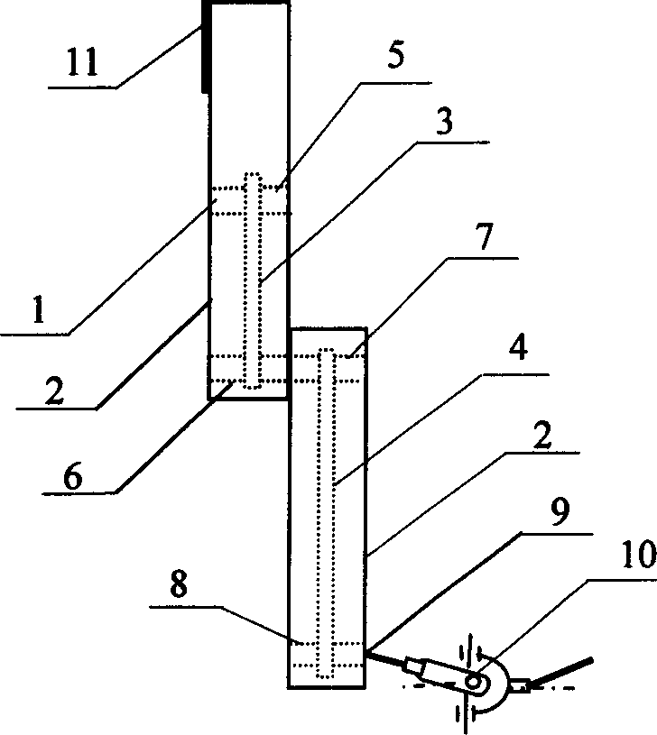
[0016] It consists of mechanical arms 1 and 2 with two rotational degrees of freedom, chain transmission devices 3 and 4, sprockets 5, 6, 7 and 8, end tooth coupling 9, universal joint 10 and counterweight device 11; the chain transmission device 3 and 4 and the sprockets 5, 6, 7 and 8 are respectively placed in the shells of the mechanical arms 1 and 2, and the sprockets 5, 6, 7 and 8 are fixed as one with the rotating shafts of the mechanical arms 1 and 2, and the universal joints 10 is connected to the shaft of the mechanical arm 2 through the end gear coupling 9; The angle of the two rotational degrees of freedom of robotic arms 1 and 2 is 0 degrees, and the direction of rotation is clockwise. The end-tooth coupling 9 is provided with 8 pairs of tooth slots connecting the shaft of the mechanical arm and the shaft of the universal joint. After engaging with the tooth slots through 8 pairs of teeth, the nuts are fastened to form a whole.

Embodiment approach 2

[0018] It consists of mechanical arms 1 and 2 with two rotational degrees of freedom, chain transmission devices 3 and 4, sprockets 5, 6, 7 and 8, end tooth coupling 9, universal joint 10 and counterweight device 11; the chain transmission device 3 and 4 and the sprockets 5, 6, 7 and 8 are respectively placed in the shells of the mechanical arms 1 and 2, and the sprockets 5, 6, 7 and 8 are fixed as one with the rotating shafts of the mechanical arms 1 and 2, and the universal joints 10 is connected to the shaft of the mechanical arm 2 through the end gear coupling 9; The angle of the two rotational degrees of freedom of mechanical arms 1 and 2 is 90 degrees, and the direction of rotation is counterclockwise. The end-tooth coupling 9 is provided with 8 pairs of tooth slots connecting the shaft of the mechanical arm and the shaft of the universal joint. After engaging with the tooth slots through 8 pairs of teeth, the nuts are fastened to form a whole.

Embodiment approach 3

[0020] It consists of mechanical arms 1 and 2 with two rotational degrees of freedom, belt transmission devices 3 and 4, pulleys 5, 6, 7 and 8, end tooth coupling 9, universal joint 10 and counterweight device 11; the belt transmission device 3 and 4 and the pulleys 5, 6, 7 and 8 are respectively placed in the shells of the mechanical arms 1 and 2, and the pulleys 5, 6, 7 and 8 are fixed as one with the rotating shafts of the mechanical arms 1 and 2, and the universal joints 10 is connected to the shaft of the mechanical arm 2 through the end gear coupling 9; The angle of the two rotational degrees of freedom of the mechanical arms 1 and 2 is 360 degrees, and the direction of rotation is clockwise. The end-tooth coupling 9 is provided with 8 pairs of tooth slots connecting the shaft of the mechanical arm and the shaft of the universal joint. After engaging with the tooth slots through 8 pairs of teeth, the nuts are fastened to form a whole.


PUM


Abstract

The invention relates to a trace self-adapting torque gearing mechanism and applied mechanics field. It is applied in the process that the torque moment transferring does not vary following the location movement. It could automatically adapt the location movement of the transferring mechanism but need not change the torque value. It is made up of mechanism two arms with rotating degree of freedom, two driving units, wheels, end tooth coupling, universal joints and balance weight device. The driving units and the wheels are separately located in the carapaces of the mechanism arms. The wheels and the rotating shafts of the mechanism arms are connected together. The universal joints are connected to the shaft of the second mechanism arm by end tooth coupling. The balance weight is fixed on the back end of the first mechanism arm. Two mechanism arms would freely rotate around the centre shaft of the wheel to form two degrees of freedom. With the two degrees of freedom of the universal joints, the mechanism could vibrate flexibly and automatically adapt the variation of the location.

Description

1. Technical field [0001] The track adaptive torque transmission mechanism of the present invention belongs to the field of mechanical engineering and applied mechanics, specifically, it is a mechanism that can automatically adapt to the position change of the transmission device without changing the torque value transmission when the torque transmission does not change with the position migration. device. 2. Technical background [0002] At present, there is no set of dynamic transmission mechanism in the published literature, which can automatically adapt to the position migration during the torque transmission process, and can automatically adapt to the position change of the transmission device without changing the torque value transmission. However, a set of dynamic trajectory adaptive torque transmission mechanism is urgently needed in various dynamic torque transmission processes. 3. Contents of the invention [0003] The purpose of the trajectory adaptive torque t...

Claims


Application Information

Patent Timeline
IPC IPC(8): F16H7/00
Inventor 李元宗武利生张晓东郭俊
Owner TAIYUAN UNIV OF TECH
Why Eureka
Try Eureka