Massaging device and bed

A driving device and mattress technology, which is applied in the direction of pneumatic massage, vibration massage, kneading massage equipment, etc., can solve the problems such as the limitation of options for adjusting the massage intensity

Inactive Publication Date: 2005-11-09
TOSHIBA TEC KK +1
View PDF1 Cites 7 Cited by
  • Summary
  • Abstract
  • Description
  • Claims
  • Application Information

AI Technical Summary

Problems solved by technology

[0006] In order to change the massage intensity, the user of the massage device cannot use other methods except for the adjustment of the air pressure in the air supply

Method used


Image

  • Massaging device and bed
  • Massaging device and bed
  • Massaging device and bed

Examples


Embodiment Construction

[0030] Below, refer to Figure 1 to Figure 6 , to illustrate the first embodiment of the present invention.

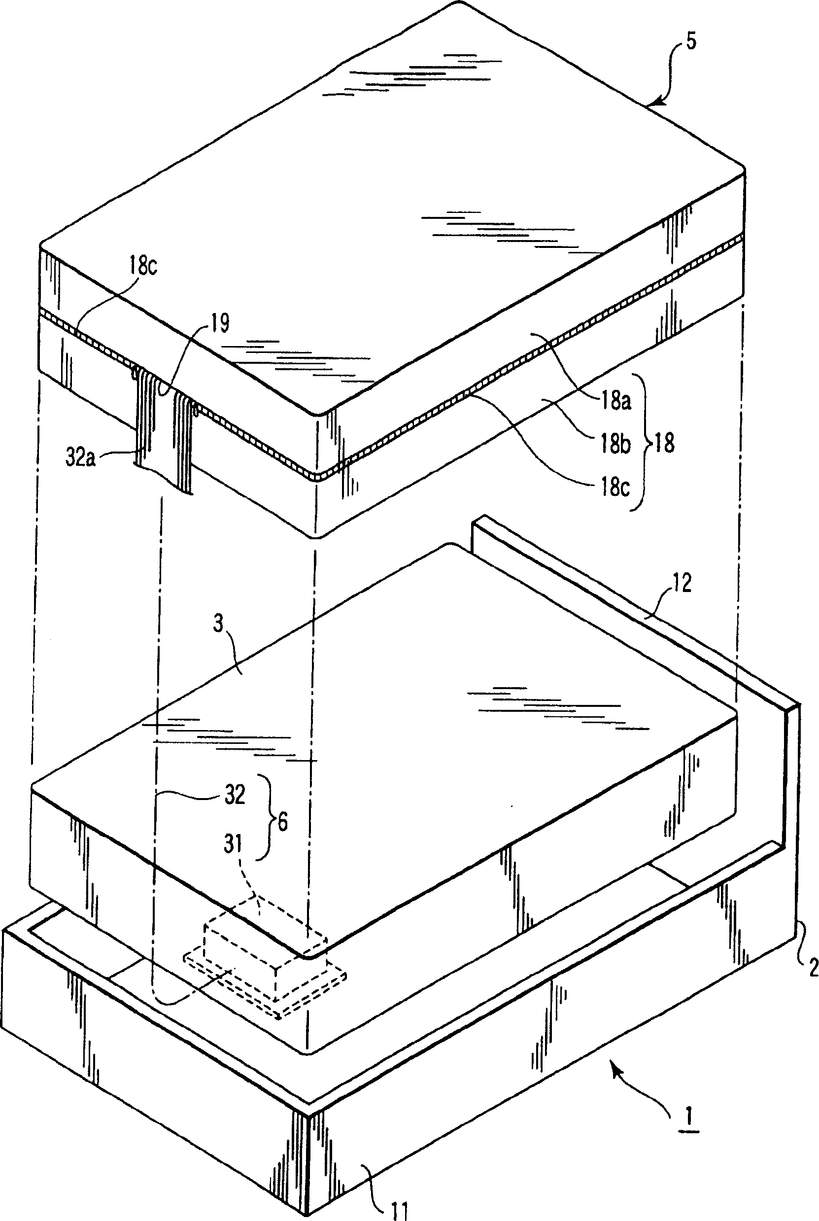
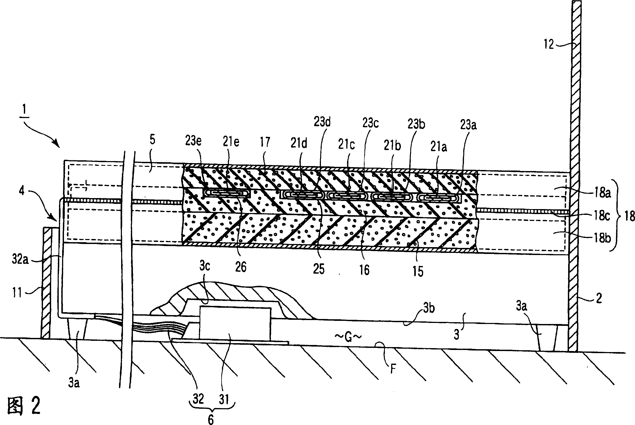
[0031] figure 1 And the bed 1 shown in FIG. 2 includes: a bed frame 2 , a basic mattress 3 , and a cushion type massage device 4 . The basic mattress 3 is used as a lower mattress.

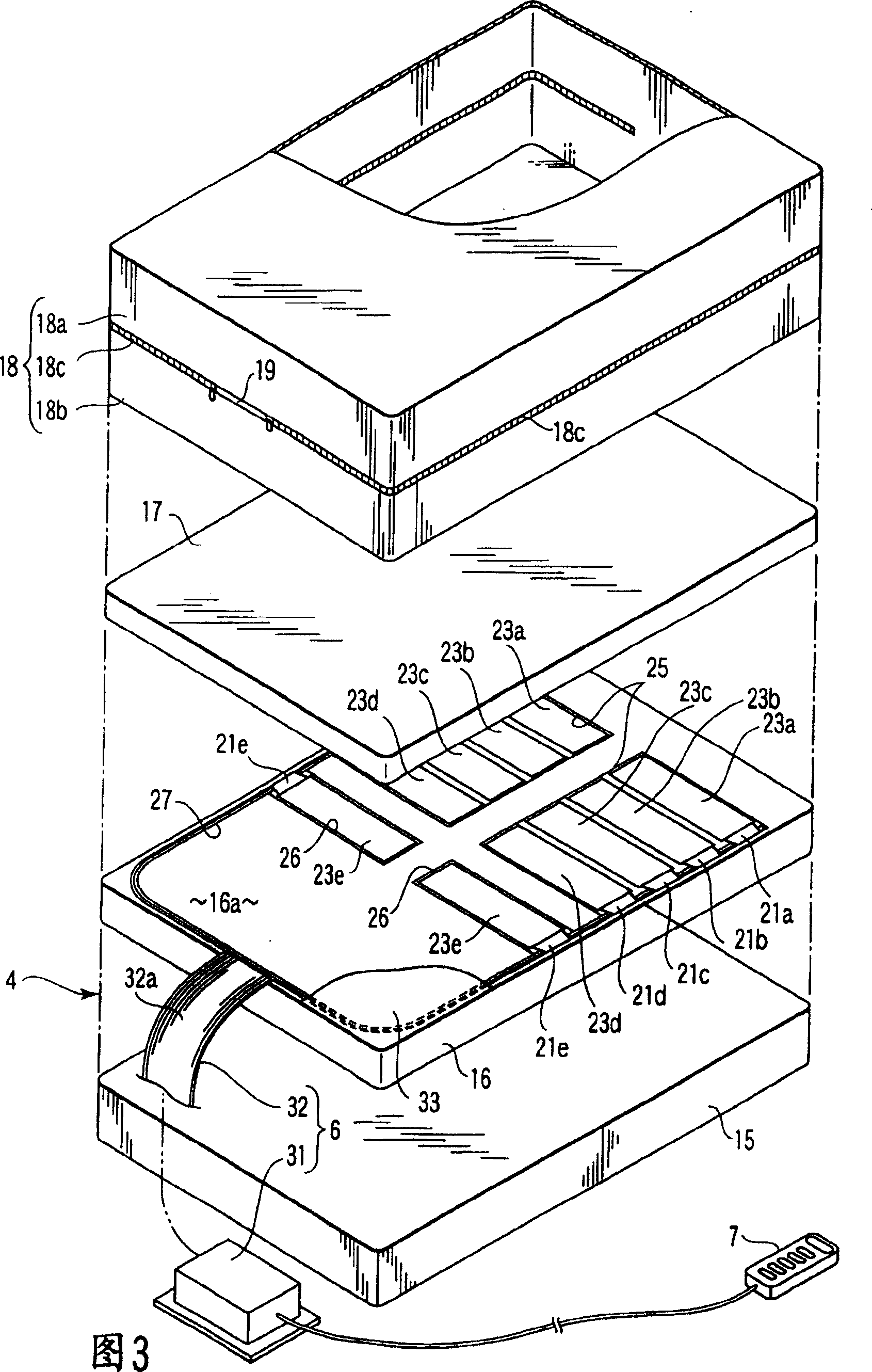
[0032] The massage device 4 comprises: an upper mattress 5, an air supply and exhaust device 6, and a remote controller 7 (referring to FIG. 3 ). The upper mattress 5 has a massage function. The air supply and exhaust device 6 functions as a driving device. The remote controller 7 functions as an operation unit. An upper mattress 5 is detachably placed on the basic mattress 3 .

[0033] The bed frame 2 is made of wood or the like. The bed frame 2 includes: a frame portion 11 and a headboard 12 . The frame portion 11 has a rectangular frame shape slightly larger than the basic mattress 3 . In the illustrated example, the frame portion 11 is placed directly on the floor (installatio...


PUM


Abstract

A massaging device comprises a mattress (5) having massaging elements (21a-21e) attached thereto. The mattress (5) comprises a mattress base (15), a plurality of mats (16, 17), and a mattress cover (18). The base (15) is vertically elastically deformable. The mats (16, 17) made of cushion material are superposed and can be independently handled; they are removably laminated to the base (5). Of the mats (16, 17), one mat (17) has an air bags (21a-21e) attached thereto. The cover (18) receives the base (15) and removably receives the mats (16, 17).

Description

technical field [0001] The present invention relates to a massaging member equipped with, for example, an inflated and contracted air bag, a massaging device capable of massaging a human body on a mattress, and a bed equipped with such a massaging device. Background technique [0002] A mat type massage device for massaging a human body on a mat is known from JP-A-2002-65783. The mat that this massage device is equipped with includes: a mat main body, a main body cover, and a plurality of air bags. The cushion main body is formed by stacking a cushioning upper layer cushion member, a middle layer cushion member, and a lower layer cushion member in this order. The main body cover wraps the cushion main body detachably from the outside. Multiple air pockets are mounted on the surface of the mat. More specifically, a plurality of outer bags are provided on the surface of the main body cover. Air bags are contained one by one in each of these outer bags. [0003] In the mas...

Claims


Application Information

Patent Timeline
IPC IPC(8): A61H7/00A47C27/00A47C27/10A47C27/18A47C31/10A61G7/057A61H1/00A61H23/04
CPCA47C27/082A47C27/15A61H2201/0142A61G7/05776A47C27/18A61H2203/0456A61H9/0078A47C27/10
Inventor 安晟镐山崎靖久村田勉
Owner TOSHIBA TEC KK
Why Eureka
Try Eureka