Chaotic control method in monitoring on-line state of large centrifugal fan

A centrifugal fan and fan technology, which is used in the testing, measuring devices, instruments and other directions of machines/structural components, and can solve problems such as misalignment, power failure, and imbalance.

Inactive Publication Date: 2005-12-21
SHANGHAI BAOSTEEL IND TECHNOLOGICAL SERVICE
View PDF0 Cites 17 Cited by
  • Summary
  • Abstract
  • Description
  • Claims
  • Application Information

AI Technical Summary

Problems solved by technology

However, in actual operation, in addition to common faults such as unbalance, misalignment, rotor cracks, oil film whirl, surge, etc., large centrifugal fans also analyze the faults of frequent alarms and even chain shutdowns of the unit. The linear analysis method seems to be unable to do what it wants, so it is of great significance to explore the nonlinear monitoring method of the fan's operating status to avoid the chain shutdown of large fans caused by excessive vibration values.

Method used


Image

  • Chaotic control method in monitoring on-line state of large centrifugal fan
  • Chaotic control method in monitoring on-line state of large centrifugal fan
  • Chaotic control method in monitoring on-line state of large centrifugal fan

Examples


Embodiment Construction

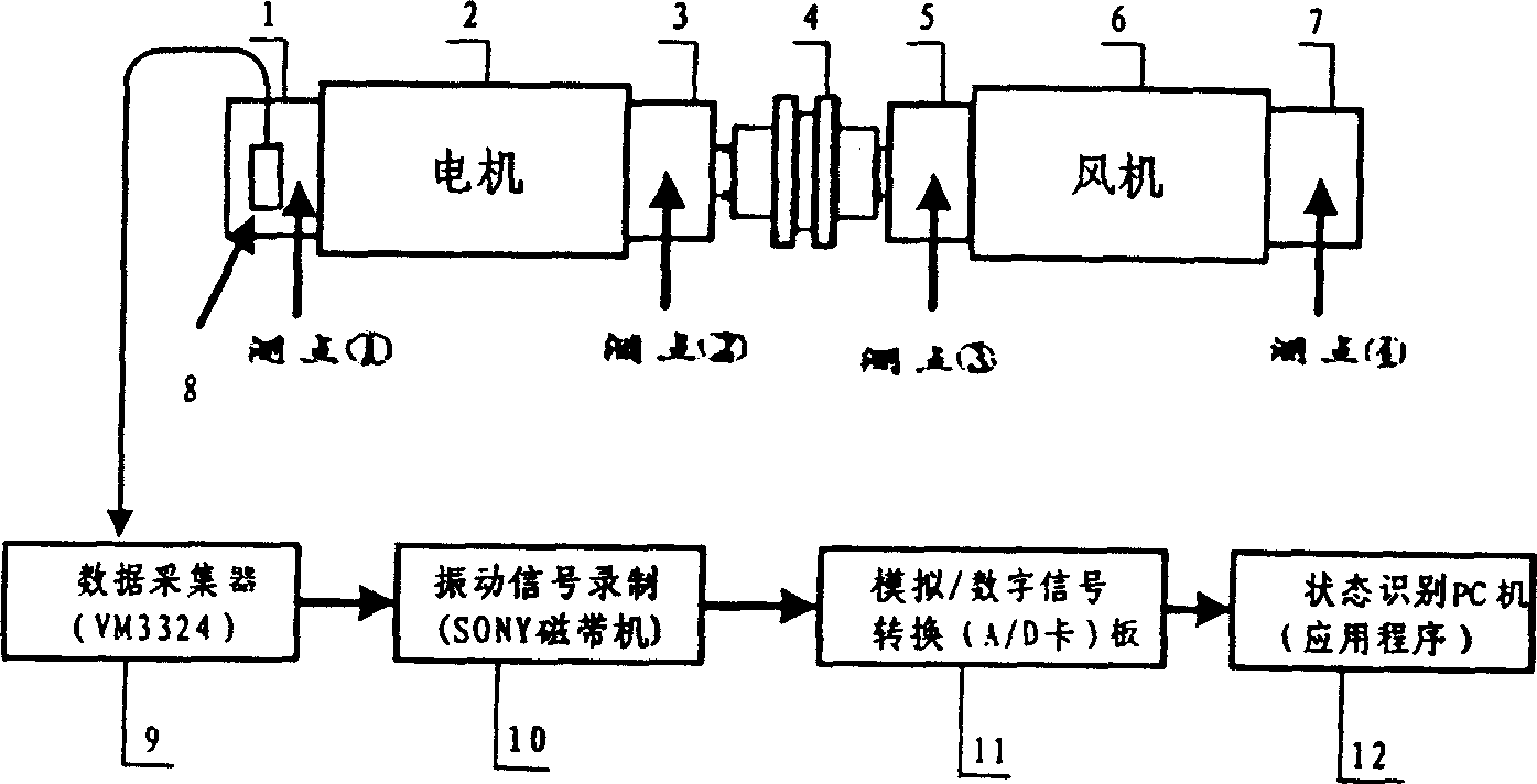
[0093] Please refer to the attached figure 1 , 2 , 3, shown in 4, the present invention is made up of parts such as motor, bearing block, shaft coupling, blower fan, sensor, tape drive, data collector and A / D conversion board, and one side of its motor (2) is free from motor The side bearing seat (1) is connected, the other side is connected with the motor load side bearing seat (3), one side of the fan (6) is connected with the fan load side bearing seat (5), and the other side is connected with the fan load side bearing seat (5). The bearing housing (7) on the free side is connected, and the bearing housing (3) on the load side of the motor and the bearing housing (5) on the load side of the fan are connected by a coupling (4);

[0094] One end of the data collector sensor (8) is installed on the free side bearing housing (1) of the motor, and its other end is connected with the input end of the data collector (9) module, and the output end of the data collector (9) module ...


PUM


Abstract

A chaos control method in on - line monitoring of large scale of centrifugal fan regulates parameters of control valve of fan flow rate, pressure or speed in Liapunov index test method for monitoring fan vibration by utilizing method of selecting dynamics delay constant tau and on - line monitoring method of chaotic phenomenon in running course to solve technical problem of eliminating high vibration value caused by chaos and suppressing generation of chaotic phenomenon .

Description

technical field [0001] The invention relates to a device for online state monitoring of a large centrifugal fan and a method for controlling chaos in the monitoring, in particular to a centrifugal fan applied to a dust removal fan used in the metallurgical industry. Background technique [0002] Centrifugal fans are mainly composed of impellers, casings, deflectors, collectors, air intake boxes and diffusers. The working principle of the centrifugal fan is that the centrifugal force generated when the impeller rotates at high speed makes the gas gain energy, that is, after the gas passes through the impeller, both the pressure energy and the kinetic energy are increased, so that it can be transported to a distant place. Under the action of air pressure, the outside air is continuously replenished to the center of the impeller along the suction pipe, while the gas that has obtained energy from the impeller flows into the volute, and part of the kinetic energy is converted int...

Claims


Application Information

Patent Timeline
Patent Type & Authority Applications(China)
IPC IPC(8): G01M99/00
Inventor 蔡正国
Owner SHANGHAI BAOSTEEL IND TECHNOLOGICAL SERVICE
Why Eureka
Try Eureka