Control method of network flow

A network traffic and network technology, applied in data exchange networks, digital transmission systems, electrical components, etc., can solve problems such as slow control speed, inability to increase and decrease TF smoothing processing, and few TF optional formats, and achieve a smooth window. Changes in size, avoid getting stuck in a congested state again, and quickly control the effect of network congestion

Inactive Publication Date: 2010-07-07
HUAWEI TECH CO LTD
View PDF1 Cites 0 Cited by
  • Summary
  • Abstract
  • Description
  • Claims
  • Application Information

AI Technical Summary

Problems solved by technology

[0005] First, the maximum TF of the transmission format is controlled. Although the amount of data on the air interface is reduced, each user can still send data in each TTI, which reduces the load on the air interface to a limited extent, and the probability of collision between users is relatively high, resulting in the probability of mutual interference. larger
[0006] Secondly, the control of uplink congestion needs to pass network layer signaling, and the control speed is relatively slow
Moreover, if there is a large interference in the system, the transmission of network layer signaling may easily cause the reset of the sign

Method used


Image

  • Control method of network flow
  • Control method of network flow
  • Control method of network flow

Examples


specific Embodiment 1

[0084] Figure 4 is a flow chart of a method for network flow control according to a preferred embodiment of the present invention, from Figure 4 It can be seen that the method includes the following steps:

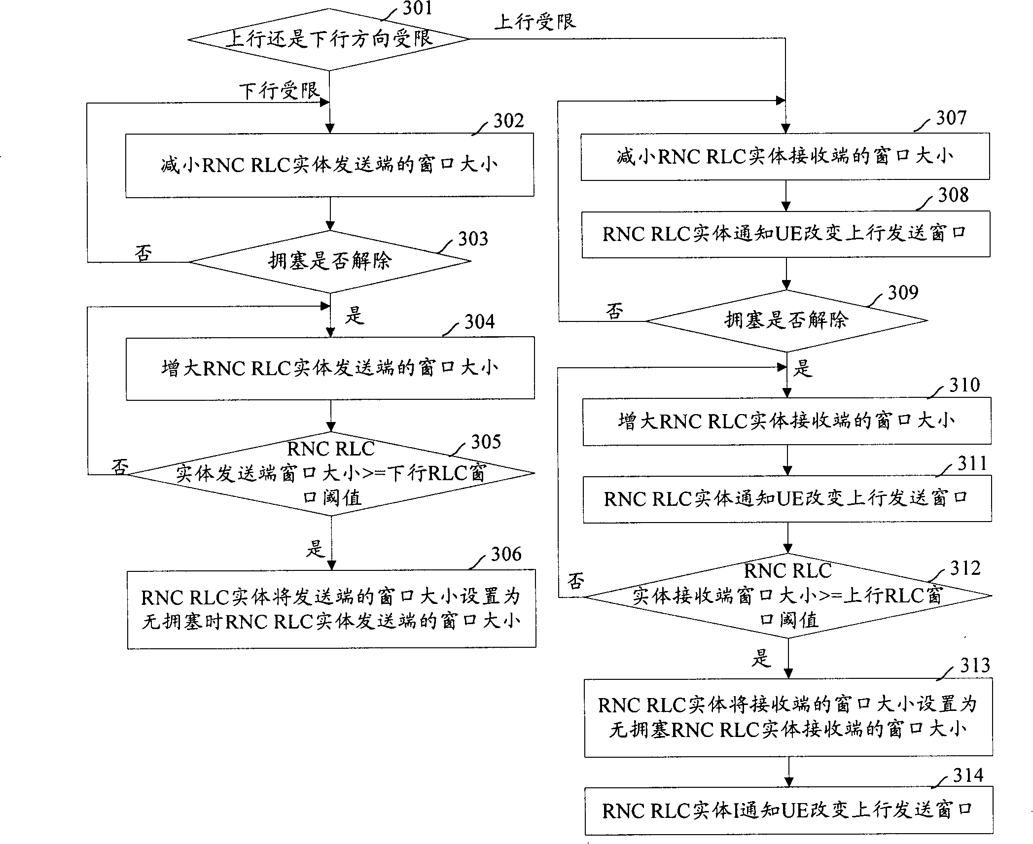
[0085] Step 401: Determine whether the downlink direction or the uplink direction is limited when the congestion occurs, if the downlink direction is limited, go to step 402; if the uplink direction is limited, go to step 409.

[0086] Step 402: Determine the downlink flow control RLC window size to ensure the downlink PS service rate under the ideal air interface quality (no bit error) by formula 1:

[0087] Downlink flow control RLC window size = downlink PS service rate (kbps) × air interface delay (s) /

[0088] (TB length-MAC header length-RLC header length)(bit) (1)

[0089] Among them, the downlink PS service rate is the PS service rate determined by the network side according to the current downlink network load level; the air interface delay is the...

specific Embodiment 2

[0123] Figure 5 is a flow chart of a method for network traffic control according to another preferred embodiment of the present invention, from Figure 5 It can be seen that the method includes the following steps:

[0124] Step 501: Determine whether the congestion occurs in the downlink direction or the uplink direction. If the downlink direction is limited, go to step 502; if the uplink direction is limited, go to step 509.

[0125] Step 502: Determine the sender flow control ratio W according to formula 7 according to the transmission rate of the downlink traffic when there is congestion and no congestion DOWN :

[0126] W DOWN = Downlink PS service rate during congestion (kbps) /

[0127] Downlink PS service rate without congestion (kbps) (7)

[0128] The downlink PS service rate when congested is the downlink PS service rate determined by the network side according to the current downlink network load level; the downlink PS service rate when there is...


PUM


Abstract

When the network congestion is detected, decreases the window of transmission end of RLC entity at RNC side, or decreases window of reception end of RLC entity at RNC side, and indicates RLC entity at UE side to change window of transmission end. When the network congestion is released, gradually increases the window of reception end of RLC entity at RNC side, or gradually increases window of reception end of RLC entity at RNC side and window of transmission end of RLC entity at UE side. When the size of window exceeds preset value, recovers windows size configured at no congestion time.

Description

technical field [0001] The invention relates to wireless resource management technology, in particular to a method for network flow control. Background technique [0002] During wireless signal transmission, packet switching (Packet Switch, PS) services have burst characteristics, and a large amount of burst data may lead to network congestion and system stability degradation. Therefore, how to quickly and effectively implement flow control to recover the network from the congested state is one of the key technologies of the radio resource management technology. [0003] The current traffic control method generally adopts the method of controlling the Transport Format Combine Set (TFCS) of the transport channel, and reduces the transport format of the transport channel corresponding to the PS service through the transport channel reconfiguration signaling of the Network Layer (L3). (Transport Format, TF), TF is n×the length of the transport block (Transport Block, TB), wher...

Claims


Application Information

Patent Timeline
IPC IPC(8): H04L29/02H04L12/56H04L12/801
Inventor 李伽汤正华楚志远张华
Owner HUAWEI TECH CO LTD
Why Eureka
Try Eureka