Ship lock electrical energy generation

A ship lock and electric energy technology, applied in ship locks, traditional hydroelectric energy, hydropower, etc., can solve problems such as difficult recycling

Inactive Publication Date: 2006-01-04
GENERAL ELECTRIC CANADA INC A CO OF CANADA
View PDF2 Cites 3 Cited by
  • Summary
  • Abstract
  • Description
  • Claims
  • Application Information

AI Technical Summary

Problems solved by technology

Therefore, the flow rate is usually large at the beginning and then decreases toward the end of the water transfer cycle until the flow rate becomes relatively small, making it difficult to recover water energy to generate electricity

Method used


Image

  • Ship lock electrical energy generation
  • Ship lock electrical energy generation

Examples


Embodiment Construction

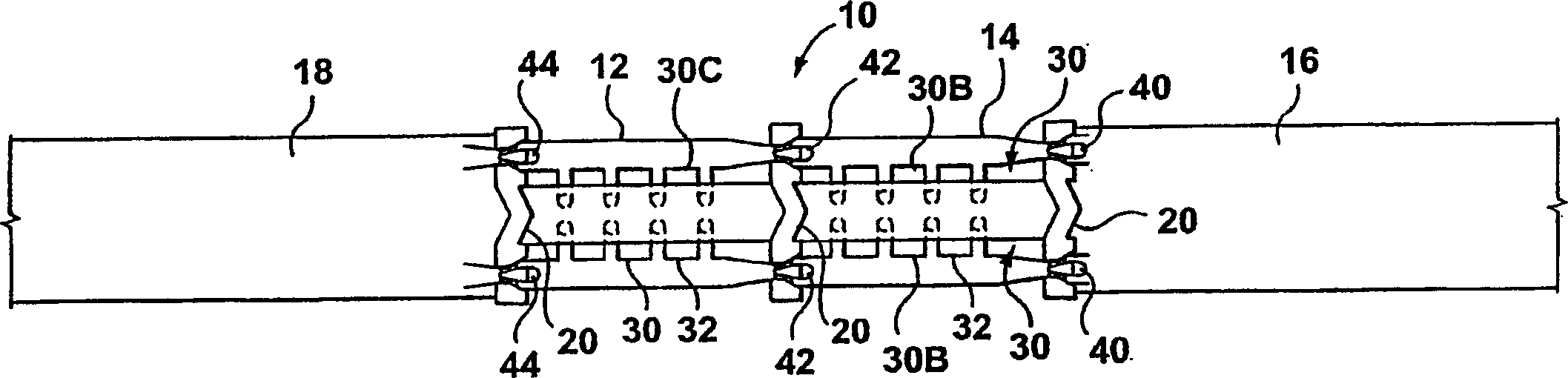
[0021] refer to figure 1 with 2 , shows a canal lock system 10 utilizing two locks 12 and 14 located between an upper body of water 16 and a lower body of water 18 respectively. It should be understood that the exemplary number of locks between bodies of water 16 and 18 is two, but could be just one or three or more locks.

[0022] Each lock 12 and 14 has a pair of gates 20 spaced apart from each other to allow boats to enter and exit the locks 12 and 14 when the gates are alternately opened and closed. Locks 12 and 14 share a common gate located therebetween.

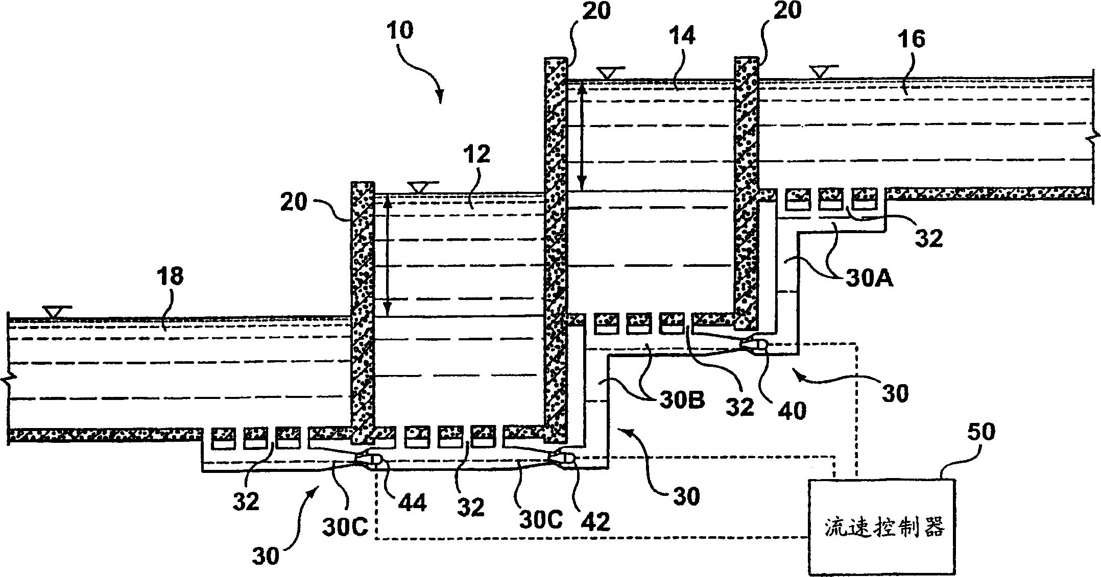
[0023] A fluid communication passage 30 extends between the bodies of water 16 and 18 for communicating the upper body of water 16 to the locks 12 and 14 , and to the lower body of water 18 . Fluid communication pathway 30 is an underground conduit that communicates with bodies of water 16 and 18 and locks 12 and 14 through controlled inlets 32 on the bottom of the canal lock system.

[0024] refer to figure 2 , ...


PUM


Abstract

A navigation lock makes use of a water turbine and / or a pump-turbine to adjust the speed of water to flow through the navigation lock to be a approximately constant value during transfer and circulation of the main part of water, thus reducing the total energy of a press head which is lost and reclaiming the unused water power to produce electrical energy. Different water levels of two opposite sides of the navigation lock produce potential water power. The loss of total head is significantly reduced in a given period through adjustment of flow, thus facilitating optimization of reclamation of water energy.

Description

technical field [0001] The present invention relates to a method and system for generating electrical energy during changes in water level in a ship lock. Background technique [0002] Typically, in canal systems, locks connect two bodies of water at different water levels by alternately falling and rising water levels in the locks. Locks use gravity to transfer a volume of water from one side of the lock to the other. Once the water level equalizes, the gates are opened to allow ships to pass. [0003] US Patent No. 4,310,769, issued January 12, 1982, teaches a ship lock system with one or more underground hydroelectric pumped storage units that generate electrical energy. When the lock level is lowered, the water drains from the lock into a lower cistern. Water flows through the canal and through the pump-turbine to generate electricity. Reservoirs collect water instead of letting it go downstream. The pump-turbine then draws water from the reservoir up through the ch...

Claims


Application Information

Patent Timeline
Patent Type & Authority Applications(China)
IPC IPC(8): E02C1/00E02B9/00
CPCE02B9/00E02C1/00Y02E10/22Y02E10/20Y02A10/30
Inventor 诺曼德·德西佩卡·弗塔
Owner GENERAL ELECTRIC CANADA INC A CO OF CANADA
Why Eureka
Try Eureka