
Numerical simulation method for axial flow pump blade tip gap leakage vortex cavitation

A technology of blade tip clearance and numerical simulation, applied in CAD numerical modeling, complex mathematical operations, electrical digital data processing, etc., can solve problems such as shortage, large difference, underestimation, etc., achieve high-precision numerical prediction, and improve reliability. Effect

Active Publication Date: 2019-07-05
HOHAI UNIV
View PDF7 Cites 32 Cited by
  • Summary
  • Abstract
  • Description
  • Claims
  • Application Information

AI Technical Summary

Problems solved by technology

Since the cavitation model based on the transport equation is derived from the theory of cavitation dynamics and two-phase flow theory, it can describe the thermodynamic non-equilibrium effect of two-phase fluid and simulate the evaporation of liquid and the condensation process of water vapor; however, The establishment of this type of model failed to consider the influence of the vortex in the cavitation flow of the tip clearance leakage vortex on the cavitation phase change process, and underestimated the effect of the vortex rotation angular momentum on prolonging the cavitation life of the tip clearance leakage vortex, resulting in axial flow The prediction accuracy of pump cavitation performance is poor, and the predicted vortex cavitation flow state is quite different from the experimental observation results, and there is a shortcoming of being too short and too small
Therefore, there is still a lack of numerical simulation methods that can effectively reflect the cavitation flow characteristics of the tip clearance leakage vortex.

Method used


Image

  • Numerical simulation method for axial flow pump blade tip gap leakage vortex cavitation
  • Numerical simulation method for axial flow pump blade tip gap leakage vortex cavitation
  • Numerical simulation method for axial flow pump blade tip gap leakage vortex cavitation

Examples


Embodiment

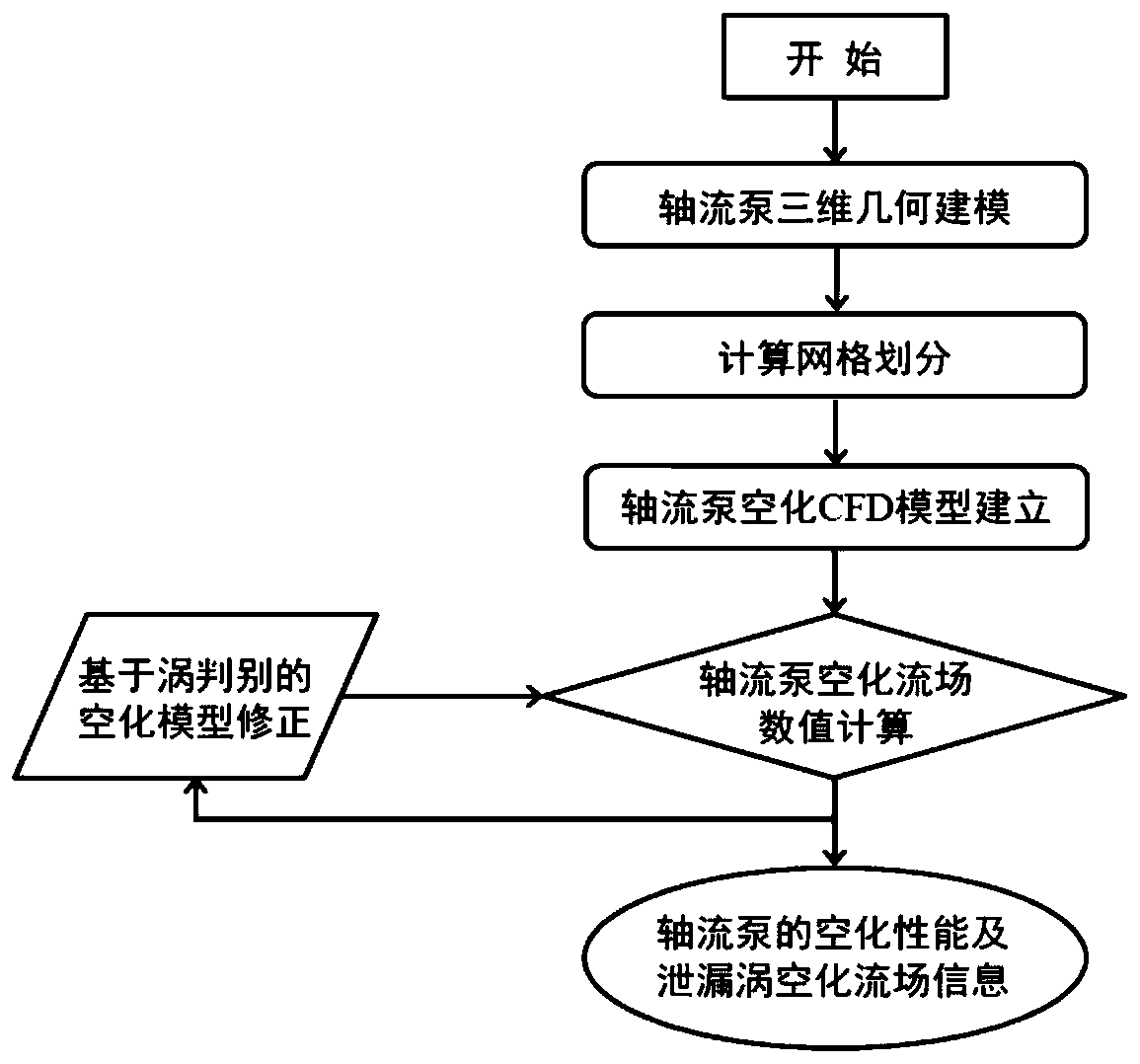
[0052] A numerical simulation method of vortex cavitation in blade tip clearance leakage of axial flow pump, such as figure 1 As shown, it is mainly realized by the following steps:

[0053] Step 1: Three-dimensional geometric modeling of the axial flow pump, according to the given design drawings of the axial flow pump, such as figure 2 As shown, the three-dimensional geometric model of the axial flow pump is established by using the geometric modeling software Croe, and the *.igs format file is output. The equivalent diameter of the inlet section of the axial flow pump inlet channel D1 = 0.75m, and the equivalent diameter of the outlet section of the outlet channel D2 = 0.4 m, the length D3=D1=0.75m of the extension section at the inlet of the axial flow pump inlet, and the length D4=5D2=2.0m of the extension section at the outlet of the axial flow pump outlet;

[0054] Step 2: Calculate mesh division, import the *.igs geometry file created and output in step 1 into the me...


PUM


Abstract

The invention discloses a numerical simulation method for axial flow pump blade tip gap leakage vortex cavitation. An axial flow pump cavitation flow field is subjected to numerical calculation by performing three-dimensional geometric modeling on the axial flow pump, dividing calculation grids and establishing a cavitation flow calculation fluid dynamics model and adopting a cavitation model corrected based on a vortex discrimination method, and the cavitation performance of the axial flow pump and the blade top gap leakage vortex cavitation flow characteristic are obtained through analysis.According to the method, the influence of vortex flow on the cavitation phase change process is fully considered, the reliability of a vortex cavitation numerical calculation result is improved, rapidand high-precision numerical prediction of axial flow pump blade tip gap leakage vortex cavitation is realized, and a good mathematical basis is laid for research on a flowing mechanism and an inhibition measure of axial flow pump blade top gap leakage vortex cavitation. meanwhile, the method can also be popularized and applied to numerical simulation research on blade top gap leakage vortex cavitation of other blade type hydraulic machines such as a mixed flow pump and a water turbine.

Description

technical field [0001] The invention belongs to the technical field of hydraulic mechanical cavitation numerical simulation, and in particular relates to a numerical simulation method for leakage vortex cavitation in the blade top clearance of an axial flow pump. Background technique [0002] Axial flow pumps play a pivotal role in many fields such as industrial and agricultural production, cross-basin water transfer, urban flood control and drainage, and ship water jet propulsion. There is a certain gap between the impeller and the shell, the important working part of the axial flow pump. Although the size of the gap is small, under the action of the pressure difference between the pressure surface and the suction surface of the blade, the fluid will pass through the gap at a high speed and mix with the main flow. The mixed entrainment forms the tip leakage vortex. The leakage vortex in the blade tip clearance can easily induce vortex cavitation, which will not only deteri...

Claims


Application Information

Patent Timeline
IPC IPC(8): G06F17/13G06F17/50
CPCG06F17/13G06F2111/10G06F30/20
Inventor 张睿费照丹
Owner HOHAI UNIV
Learn More