Tethered aquatic device with water power turbine

Inactive Publication Date: 2011-04-28
HONEYWELL INT INC
View PDF57 Cites 33 Cited by
  • Summary
  • Abstract
  • Description
  • Claims
  • Application Information

AI Technical Summary

Benefits of technology

[0007]A water current driven electric power generating apparatus and method for ge

Problems solved by technology

Commercial utilization of tidal currents and wave energy has steadily increased over the past few decades, but is well shy of providing a significant percentage of global electrical power demand.
Modern large hydro-based turbines utilize either extremely heavy step-up gea

Method used


Image

  • Tethered aquatic device with water power turbine
  • Tethered aquatic device with water power turbine
  • Tethered aquatic device with water power turbine

Examples


first embodiment

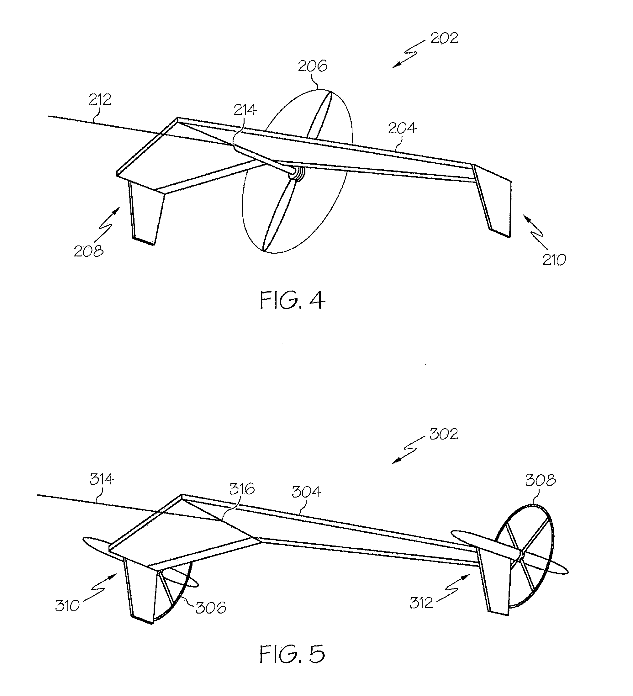
[0035]FIG. 4 illustrates a TAD 202, including a hydrofoil 204 and one trailing (relative to the direction of travel) water power turbine 206. The hydrofoil 204 is designed including a first wing tip 208 and a second wing tip 210. The TAD 202 is tethered to an anchorage or mooring point, (base station 108 of FIG. 1) via a tether 212 attached to a tether attachment point 214 located on the hydrofoil 204.

[0036]In general, trailing water power turbines are preferred to leading water power turbines for several reasons. First, trailing turbines will have a minimal effect on the flow of water over the top and bottom surfaces of the hydrofoil and a negligible effect on the lift / drag of the TAD. A leading turbine, or turbines, will extract energy from the water that passes through the rotor thus decreasing the velocity of the water flowing over the hydrofoil and reducing the lift. Second, trailing turbines will increase overall stability since the drag created by them is behind the TAD. Drag...

second embodiment

[0037]FIG. 5 illustrates a TAD 302 including a hydrofoil 304 having two trailing water power turbines 306 and 308. The hydrofoil 304 is designed including a first wing tip 310 and a second wing tip 312. A first trailing water power turbine 306 is located at the first wing tip 310 and a second trailing water power turbine 308 is located at the second wing tip 312. A tether 314 is attached to a tether attachment point 316 located on the underside of the hydrofoil 304. This configuration has the benefit of not needing winglets to reduce vortices drag. Differential drag between multiple turbines can also a degree of control authority.

third embodiment

[0038]FIG. 6 illustrates a TAD 402 including a hydrofoil 404 having two trailing water power turbines 406 and 408 and a forward facing or leading water power turbine 414. The hydrofoil 404 is designed including a first wing tip 410 and a second wing tip 412. A first trailing water power turbine 406 is located at the first wing tip 410 and a second trailing water power turbine 408 is located at the second wing tip 412. The forward facing water power turbine 414 is located at the center of the hydrofoil 404 to provide a balancing weight to the front of the hydrofoil 404. This balancing weight increases static stability as well as pitch control. A tether 416 splits into two separate tether portions, wherein a first tether portion 418 attaches at a first attachment point 420 located near the first wing tip 410 and a second tether portion 422 attaches at a second attachment point 424 located near the second wing tip 412.


PUM


Abstract

A water power turbine energy conversion device and method of generating electric power that can take advantage of water current speeds is hereinafter disclosed. The water power turbine energy conversion device includes an unmanned tethered aquatic device (TAD) connected to one end of a tether (which may include multiple shorter tethers), the other end being connected to an anchorage point. The TAD comprises a hydrofoil wing-like structure with one or more water power turbines and performs waterborne maneuvers such as cross-current tracking to increase the relative water current speed of up to about four times the true water current speed.

Description

TECHNICAL FIELD[0001]The present invention relates to sustainable energy sources, and more particularly to a water current driven electric power generating apparatus in the form of a tethered aquatic device having at least one water power turbine for energy conversion.BACKGROUND[0002]The energy contained in ocean currents represents a clean, sustainable natural resource for meeting a portion of the world's growing energy needs. The energy contained in the ocean currents can be converted to electricity. There are several areas in the ocean where currents are steady and do not shift location. An example is the Florida Straits current, located a few miles off the southern coast of Florida, near Miami.[0003]Ocean current speeds are on the order of 4 to 10 mph. Although the currents move at low speeds, the density of water is over 800 times the density of air at sea level on a standard day. Power density is directly proportional to fluid density. For example, in a 4 mph current, the powe...

Claims


Application Information

Patent Timeline
IPC IPC(8): F03B13/00F03B15/00
CPCF03B17/061Y02E10/28F05B2240/40Y02E10/30Y02E10/20
Inventor BLUMER, ERICTHURSTON, JOHNJONES, PAUL
Owner HONEYWELL INT INC
Why Eureka
Try Eureka