Pelatic sustainable energy system

Active Publication Date: 2009-10-29
ABATEMARCO MICHAEL R
View PDF21 Cites 35 Cited by
  • Summary
  • Abstract
  • Description
  • Claims
  • Application Information

AI Technical Summary

Benefits of technology

[0008]The present invention allows for the pelagic deployment of sustainable electricity generating devices in an adjustable, customizable manner, allowing for the opt

Problems solved by technology

The world's supply of fossil fuels dwindles daily.
A global energy crisis would be inevitable if the fossil fuel resources are depleted without first devising robust, sustainable solutions.
As fossil fuels become scarce and fuel prices increase, the populatio

Method used


Image

  • Pelatic sustainable energy system
  • Pelatic sustainable energy system
  • Pelatic sustainable energy system

Examples


Embodiment Construction

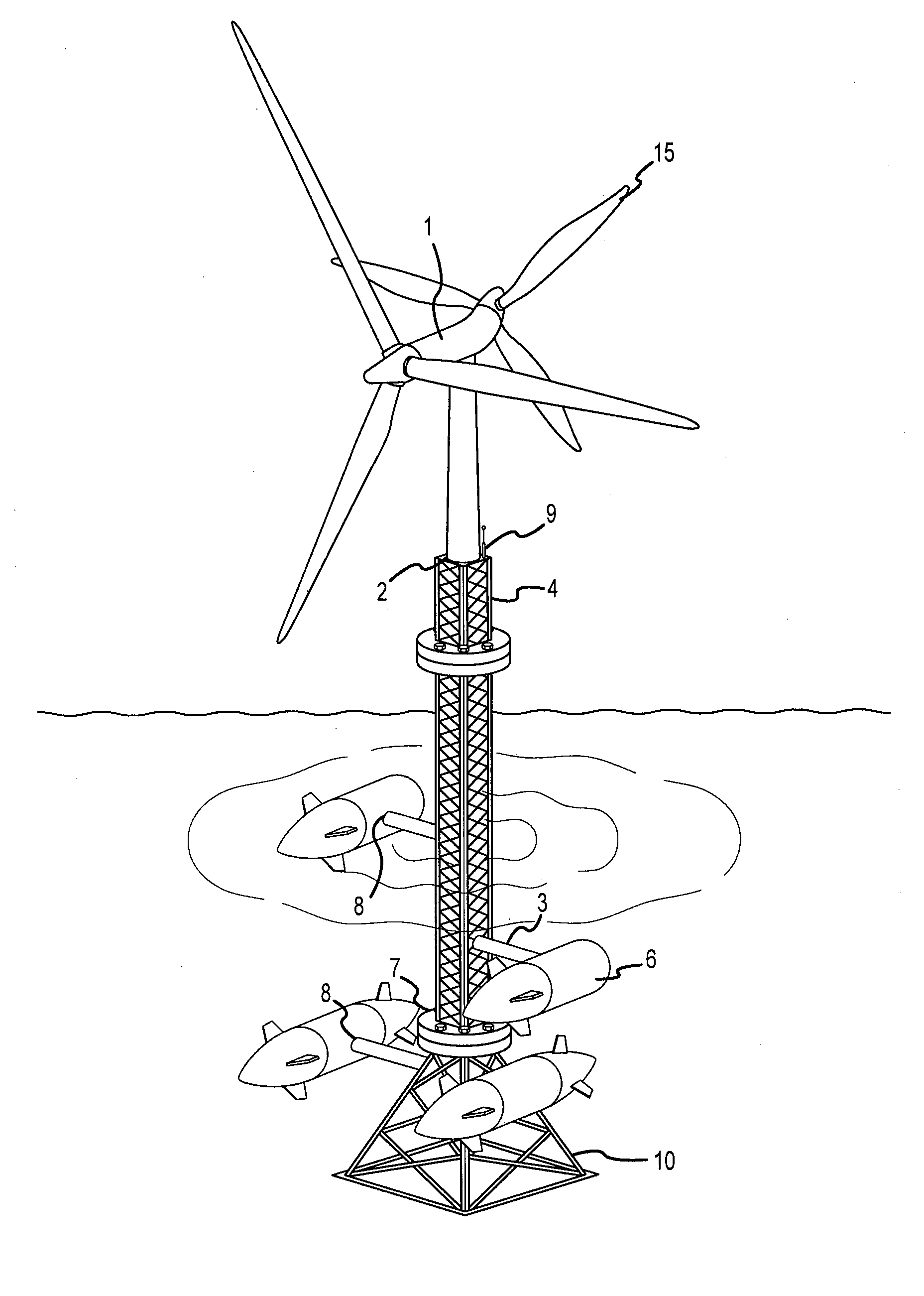
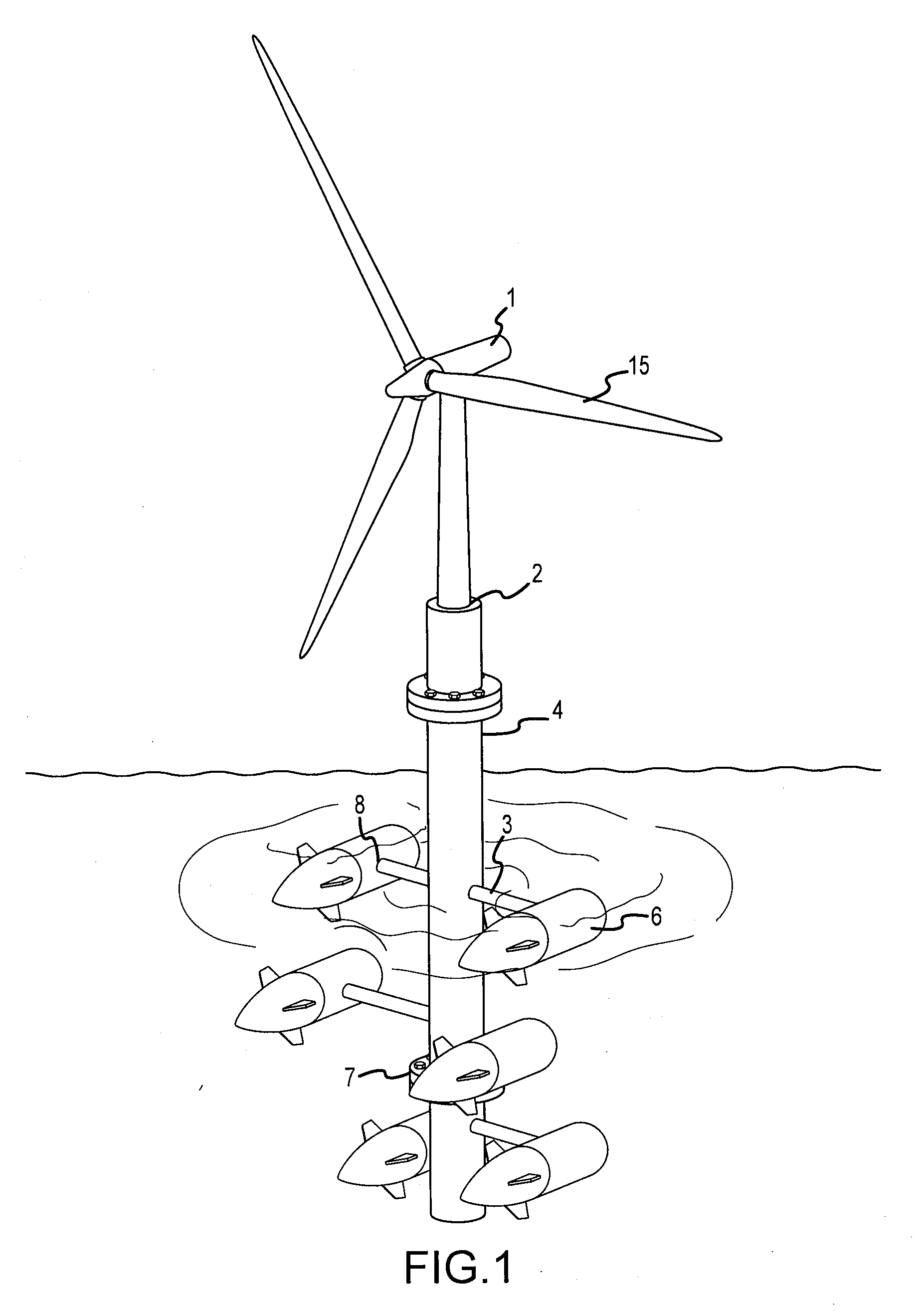
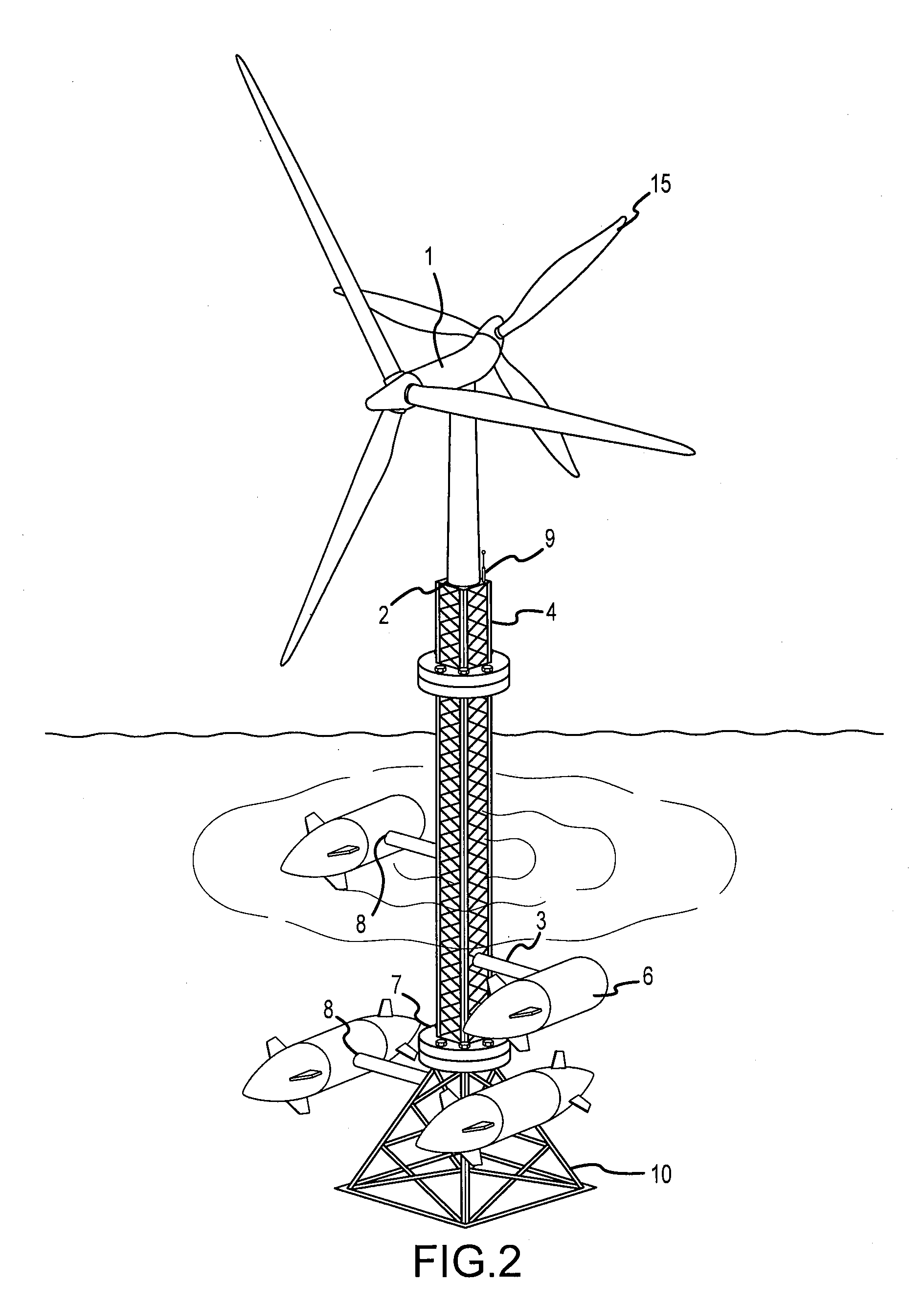
[0021]The invention is described with reference to the enclosed Figures wherein the same numbers are used where applicable. The term “water surface level” means the surface of any naturally occurring or manmade body of water. The term “electricity generating device” means any of the constituent elements of the present invention that is capable of generating electricity, specifically, a wind turbine generator, a water turbine generator, a solar panel, or any combination thereof.

[0022]The cost of constructing structures that generate power from just one source of sustainable energy is high. However, by using one structure in conjunction with multiple electricity generating devices, the present invention allows for achievement of significant efficiencies in the generation of electricity. Accordingly, the combination of multiple forms of electricity generating devices may provide an increasing marginal return on investment. Additionally, by adjusting the various electricity generating d...


PUM


Abstract

The present invention provides a sustainable energy system for pelagic deployment that may comprise a frame, at least one wind turbine generator coupled to the frame, at least one pair of water turbine generators coupled to the frame, and a rotatable joint.

Description

FIELD OF THE INVENTION[0001]The present invention includes an apparatus for pelagic deployment that can provide a sustainable source of energy. Specifically, an exemplary device features a wind turbine generator, a pair of water turbine generators, and a rotatable joint.BACKGROUND OF THE INVENTION[0002]The present invention includes an apparatus for pelagic deployment that can provide a sustainable source of energy.[0003]Now, more than ever, sustainable sources of energy are needed to both alleviate humankind's dependence on non-renewable resources and support the world's growing energy needs. The world's supply of fossil fuels dwindles daily. Coal, oil, and natural gas comprise the majority of the world's energy sources. A global energy crisis would be inevitable if the fossil fuel resources are depleted without first devising robust, sustainable solutions.[0004]At the same time, the world's human population continues to grow as more nations become industrialized. This growth requi...

Claims


Application Information

Patent Timeline
IPC IPC(8): F03B13/00F03D9/00F03B13/10
CPCF03B13/10F03B17/061F03D9/008F05B2210/18Y02E10/725F05B2240/97Y02E10/22Y02E10/28F05B2240/40F03D1/025F03D9/007F05B2240/95F05B2250/411F03D9/25F03D13/25H02S10/12Y02E10/20Y02E10/30Y02E10/50Y02E10/72Y02E10/727
Inventor ABATEMARCO, MICHAEL R.
Owner ABATEMARCO MICHAEL R
Why Eureka
Try Eureka