
Sewing machine and method for regulating drive force of its needle

A technology for sewing machines and machine needles, applied in the direction of sewing machine needle holders, sewing machine components, sewing equipment, etc., which can solve problems such as unusable, insufficient length margin, and difficult belt disassembly, so as to improve workability and suppress manufacturing costs , The effect of shortening the working time

Inactive Publication Date: 2006-03-15
JUKI CORP
View PDF1 Cites 3 Cited by
  • Summary
  • Abstract
  • Description
  • Claims
  • Application Information

AI Technical Summary

Problems solved by technology

Therefore, the existing cover cannot be used, and the problem of raising the manufacturing cost arises.
[0008] And, usually, the belt is properly installed between the pulley provided on the main shaft outside the sewing machine frame and the pulley provided on the sewing machine motor as the driving source, and the length does not have sufficient margin. Therefore, when the flywheel When the diameter becomes larger, the removal of the belt becomes difficult

Method used


Image

  • Sewing machine and method for regulating drive force of its needle
  • Sewing machine and method for regulating drive force of its needle
  • Sewing machine and method for regulating drive force of its needle

Examples

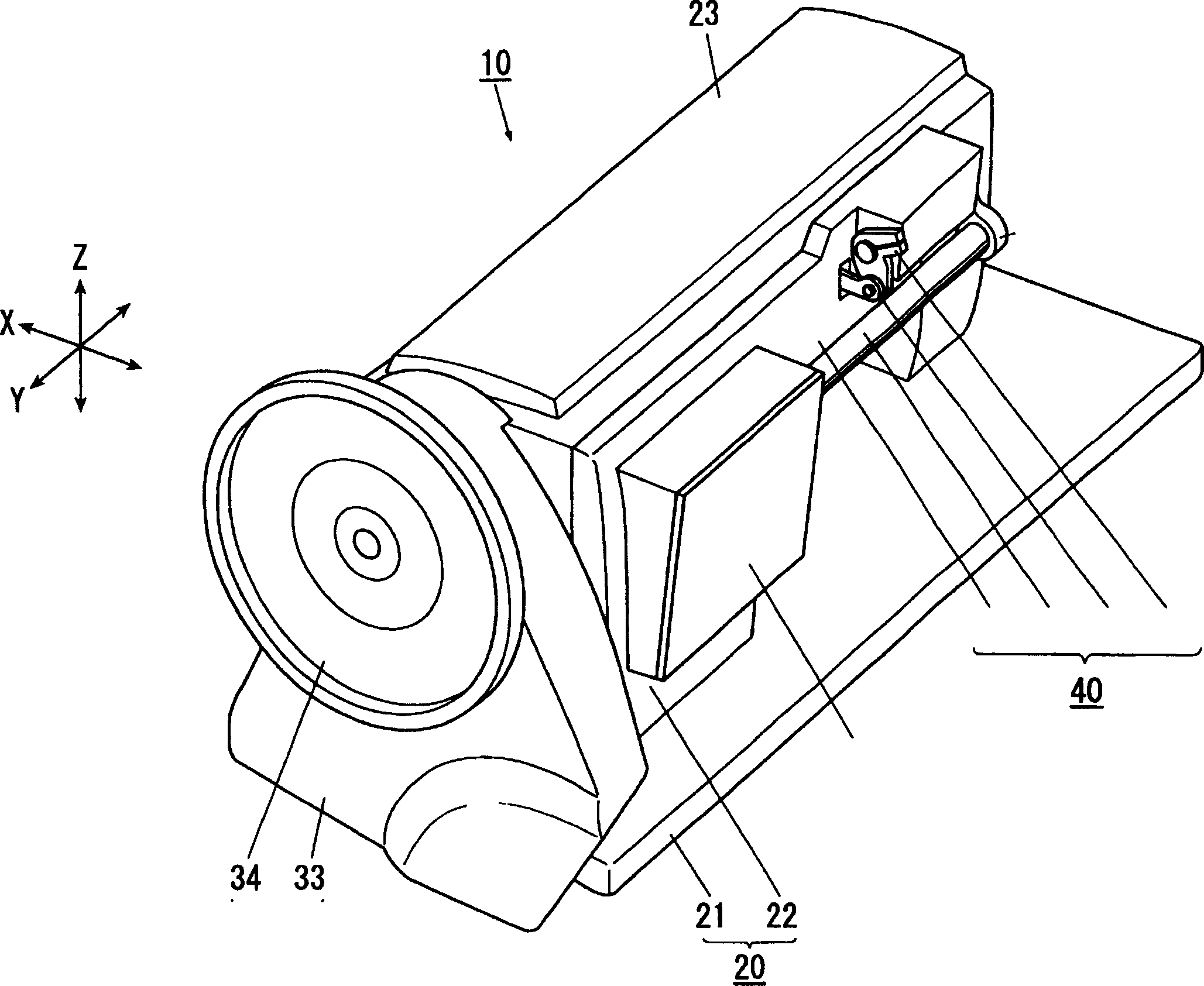

Embodiment Construction

[0025] (Overall configuration of the embodiment of the invention)

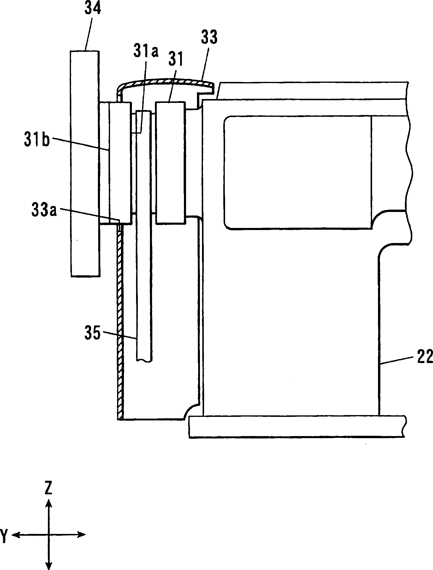
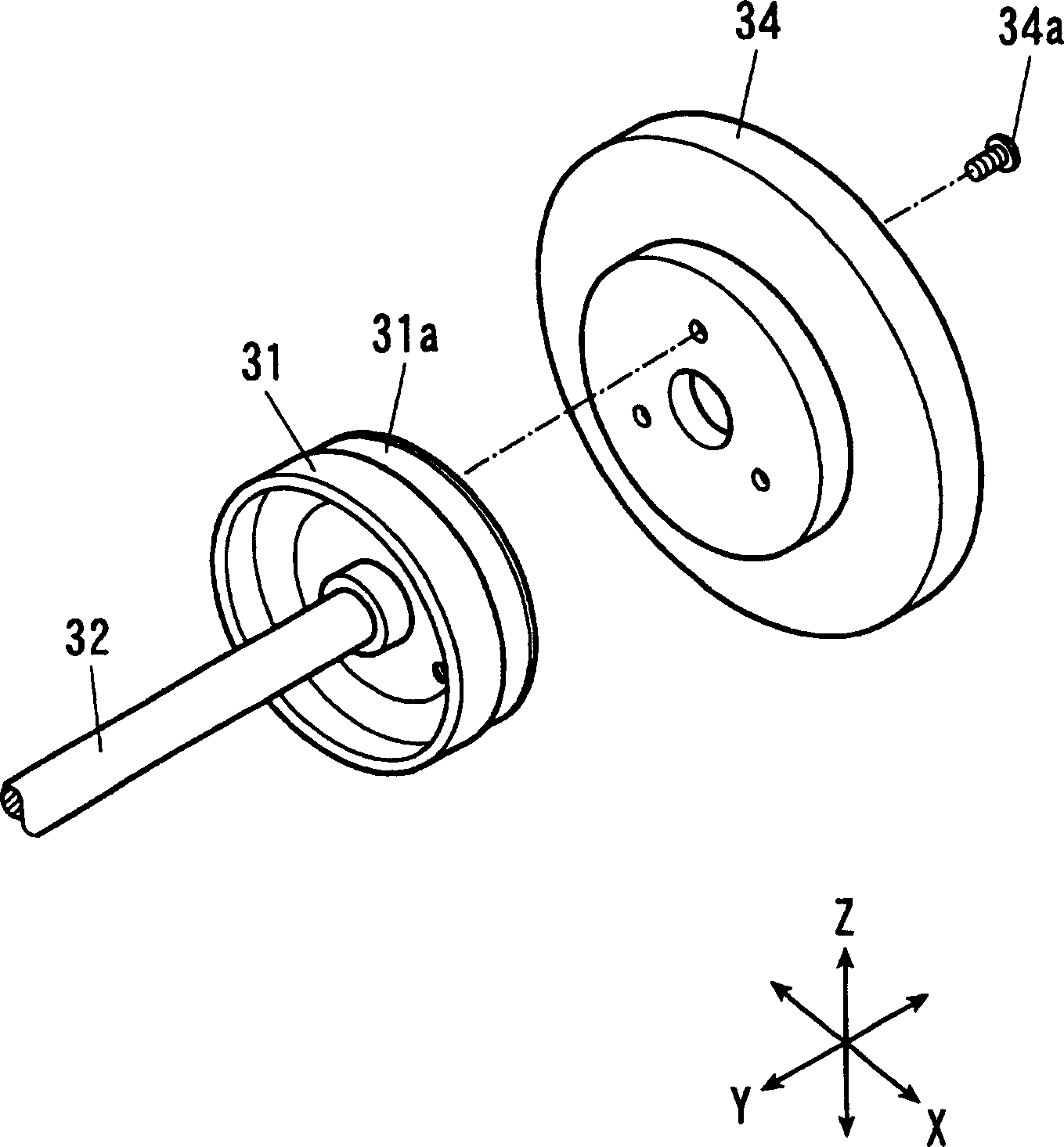
[0026] Below, refer to the attached Figure 1~3 , to describe the embodiments of the present invention in detail.

[0027] The above-mentioned lockstitch sewing machine 10 has a needle bar up and down mechanism (not shown) that moves the needle up and down, and a bottom mechanism that feeds the cloth as the sewing object placed on the needle plate 12 from below to a predetermined cloth feeding direction. The cloth feeding device (illustration omitted), and the sewing machine frame 20 that accommodates the needle bar up and down mechanism and the lower cloth feeding device, and the sewing machine frame 20 that can be loaded and unloaded on the sewing machine frame 20 and sends the cloth on the needle plate 12 from above to the prescribed cloth feeding direction. Cloth feeding device 40.

[0028] In the following description, the vertical up and down direction is taken as the Z-axis direction, and the longitud...


PUM


Abstract

The invention provides a sewing machine capable of quickly changing a penetration force of a needle and to provide its needle driving force adjusting method. A flywheel 34 is a flange-shaped rotating body having a diameter larger than that of a pulley 31. The flywheel 34 is detachably mounted on the end face 31b of the pulley 31 by three set screws 34a concentrically to the pulley 31. In sewing, when a material to be sewn is thick or hard, the sewing needle does not smoothly penetrate therethrough. The mounting of the flywheel 34 on the pulley 31 can increase the mass around an arm shaft 32, and improve an inertia moment around the arm shaft 32 driving the sewing needle to strengthen the penetration force of the sewing needle and suppress the effect of torque fluctuation. In especially, the flywheel 34 has the diameter larger than that of the pulley 31 to effectively improve the inertia moment and provide a stable penetration force to the sewing needle.

Description

technical field [0001] The present invention relates to a sewing machine which moves a needle up and down according to the rotation of a pulley connected to a driving source through a belt, and a method for adjusting the driving force of the needle. Background technique [0002] Conventionally, a configuration is known in which a main shaft of a sewing machine to which a pulley is fixed is rotated to move a needle up and down based on the rotation of a pulley connected to a drive source such as a motor via a belt. In such a sewing machine, since the penetration force of the needle required in a sewing machine that sews separately according to the material or thickness of the object to be sewn is different, it is necessary to adjust the penetration of the needle according to the type of the object to be sewn. force. Therefore, a method of replacing pulleys with different weights was adopted. [0003] Generally, as the weight of the pulley increases, the moment of inertia du...

Claims


Application Information

Patent Timeline
Patent Type & Authority Applications(China)
IPC IPC(8): D05B55/14
Inventor 新井富夫川岛静夫渡部贵志
Owner JUKI CORP
Learn More