Apparatus and method of releasing disk in optical disk player

A disk loading and chucking technology, applied in the field of disk unclamping devices, can solve the problems of ineffective transmission of power and high power

Inactive Publication Date: 2006-03-15
SAMSUNG ELECTRONICS CO LTD
View PDF0 Cites 1 Cited by
  • Summary
  • Abstract
  • Description
  • Claims
  • Application Information

AI Technical Summary

Problems solved by technology

Since the slide 16 is large and the transfer of power is not very efficient, considerable power is required to transfer power from the slide 20 to the guide levers 13 and 14 and the locking lever 12

Method used


Image

  • Apparatus and method of releasing disk in optical disk player
  • Apparatus and method of releasing disk in optical disk player
  • Apparatus and method of releasing disk in optical disk player

Examples


Embodiment Construction

[0029] Embodiments of the present invention will now be described in detail, examples of which are shown in the accompanying drawings in which like reference numerals denote like elements. Embodiments of the present invention will be described below with reference to the drawings.

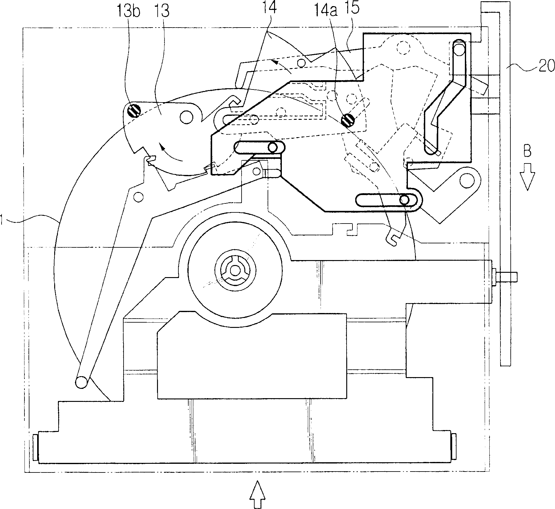
[0030] From Figure 6 and 7 It can be seen that the disc release device 100 for a disc player according to an embodiment of the present invention includes a first unit 401 , a second unit 402 , a third unit 403 and an elastic member 258 . The disk unclamping device 100 operates to connect each of the first and second guide pins 318 and 352 provided on the first and second pivot plates 310 and 350 with the disk 1 or 352 loaded into the chuck position. 2 Release. Its components include a main chassis 150, first and second sliders 210 and 220 and a transfer roller 620 for transferring the tray.

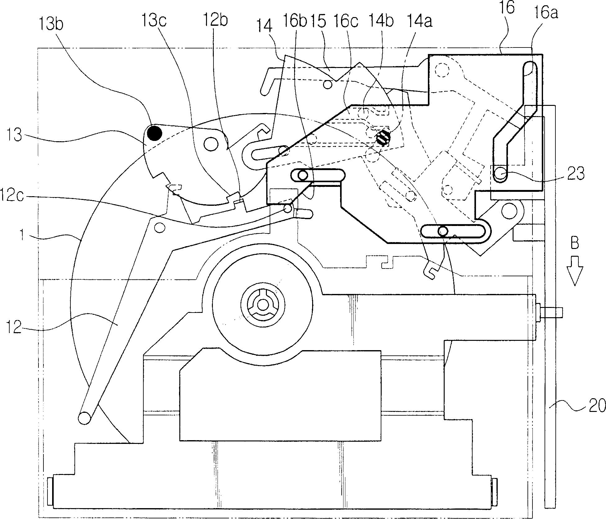
[0031] The first unit 401 includes a push lever 450 , a guide pin 464 , a slot 454 , a pivot pin 458 ,...


PUM


Abstract

Disclosed are an apparatus and method of releasing a disk. The disk releasing apparatus includes a first unit operating in cooperation with the second pivot plate to selectively couple the slider to the transmission unit, and a second unit operating in cooperation with the slider to release the second pivot plate from the disk. It can reduce the number of components, and decrease a power loss generated at the transmission.

Description

technical field [0001] This invention relates to disc players, and more particularly, the present invention relates to an apparatus and method for releasing a disc loading guide from a loaded disc. Background technique [0002] Generally, a disk drive operates to record / reproduce information on / from a disk-shaped medium such as CD, DVD, DVD-ROM, and the like. The disc drive includes a loading unit for loading a disc into a position where information is recorded / reproduced on / from the disc. After the disc is inserted into the main body of the disc player using the loading unit, the disc is placed on a turntable and then clamped by a chucking unit so as to be rotatable. During rotation of the disc on the turntable, an optical sensor moves in the radial direction of the disc to record information on the disc or to reproduce information from the disc. [0003] In particular, due to miniaturization and space limitations of disc players, disc loading units are recently used to d...

Claims


Application Information

Patent Timeline
Patent Type & Authority Applications(China)
IPC IPC(8): G11B17/04G11B33/00
CPCG11B17/05G11B17/0515G11B17/0404G11B17/04
Inventor 李庭在
Owner SAMSUNG ELECTRONICS CO LTD
Why Eureka
Try Eureka