Automatic assembling mechanism for long tail clamp

An automatic assembly and assembly mechanism technology, applied in the direction of assembly machines, metal processing equipment, manufacturing tools, etc., to achieve the effect of reliable action, high assembly precision, and convenient installation and maintenance

Inactive Publication Date: 2006-03-22
ZHEJIANG UNIV OF TECH
View PDF0 Cites 35 Cited by
  • Summary
  • Abstract
  • Description
  • Claims
  • Application Information

AI Technical Summary

Problems solved by technology

[0003] The invention solves a series of shortcomings caused by manual assembly of long tail clips at present, and provides an automatic assembly mechanism for long tail clips assembled by using mechanical claws instead of human hands

Method used


Image

  • Automatic assembling mechanism for long tail clamp
  • Automatic assembling mechanism for long tail clamp
  • Automatic assembling mechanism for long tail clamp

Examples


Embodiment 1

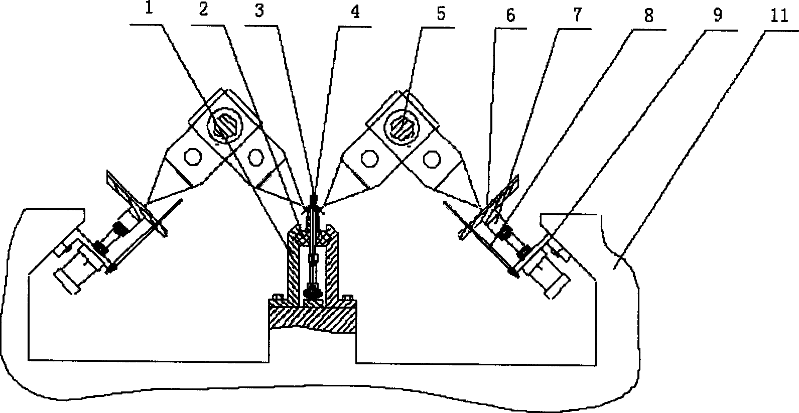
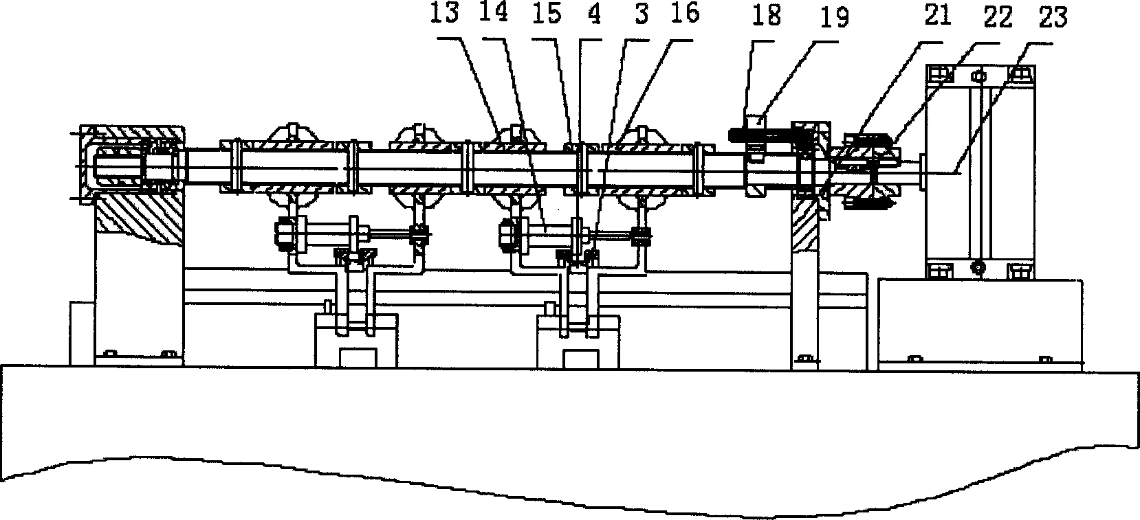
[0021] Embodiment 1: Referring to the accompanying drawings, an automatic assembly mechanism for long tail clips includes a workbench 11 on which there is a clip body positioning and conveying mechanism, a handle positioning and conveying mechanism, a handle assembly mechanism, and coordination and control of the above three mechanisms Action electric control device; the handle assembly mechanism includes: the spline shaft 5 connected with the swing cylinder 23, the left mechanical claw 13 and the right mechanical claw 16 are slidable and can rotate with the spline shaft and are connected to the spline shaft 5, the end cover and piston rod of the clamping cylinder are respectively connected to the left mechanical claw and the right mechanical claw; Positioning and conveying mechanism, handle positioning and matching position of conveying mechanism. The clamp body positioning and conveying mechanism includes: a fixed guide rail 1, a movable guide rail 2 that can slide in the fi...

Embodiment 2

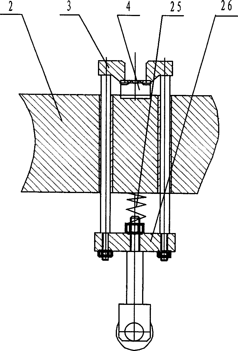
[0022] Embodiment 2: The clamping device of the clamp includes a guide rod that runs through the through hole of the movable guide rail, the upper end of the guide rod is located above the movable guide rail and a pressing plate 3 is provided, and the lower end of the guide rod is provided with a fixed plate 26. A spring 25 is arranged between the fixed plate and the movable guide rail. The movable guide rail is provided with a clamp body positioning groove. Others are the same as embodiment one.

Embodiment 3

[0023] Embodiment Three: The cylinder block 9 is provided with a guide rod 8 . The lifting trough 7 is provided with a conveying trough for conveying the handle, a handle positioning surface and a groove for the end of the mechanical claw to pass through. Described guide bar 8 is connected with lifting chute. Others are the same as embodiment one.


PUM


Abstract

The automatic assembling mechanism for long tail clamp includes work stable, clamp locating and conveying mechanism, handle locating and conveying mechanism, handle assembling mechanism, and electric controller for controlling the clamp locating and conveying mechanism, the handle locating and conveying mechanism and the handle assembling mechanism. The handle assembling mechanism includes spline shaft connected to the oscillating cylinder, right and left mechanical claws to form clamp, and clamping cylinder with end cap and piston rod connected separately to the left mechanical claw and the right mechanical claw. The present invention has high work efficiency, low production cost, high assembling precision and other advantages.

Description

(1) Technical field [0001] The invention relates to an automatic assembly mechanism for a long tail clip, in particular to an automatic assembly mechanism for a long tail clip which adopts a manipulator for quick assembly. (2) Background technology [0002] At present, whether abroad or at home, long tail clips are all assembled manually. Manual operation is labor-intensive and production efficiency is low. Due to the low price of long-tail clips, with the continuous increase of labor wages, corporate profits will decrease or even lose money. Therefore, manufacturers are eager to have long-tail clip automatic assembly machines instead of manual assembly. However, due to the small size of the long tail clip, the assembly action is complicated and the requirements are high, so there is still no automatic assembly line at home and abroad to replace manual assembly. (3) Contents of the invention [0003] The invention solves a series of shortcomings caused by manual assembly ...

Claims


Application Information

Patent Timeline
Patent Type & Authority Applications(China)
IPC IPC(8): B23P21/00
Inventor 郑欣荣张宪计时鸣熊四昌张为民徐强
Owner ZHEJIANG UNIV OF TECH
Why Eureka
Try Eureka