Optical disk drive apparatus
A technology of optical disc drive and optical pickup device, which is applied in the direction of coupling device, optical recording head, optical head manufacturing, etc., can solve the problems of inability to insert flexible substrate into connectors, strict thickness restrictions, etc. Effect
- Summary
- Abstract
- Description
- Claims
- Application Information
AI Technical Summary
Problems solved by technology
Method used
Image
Examples
Embodiment 1
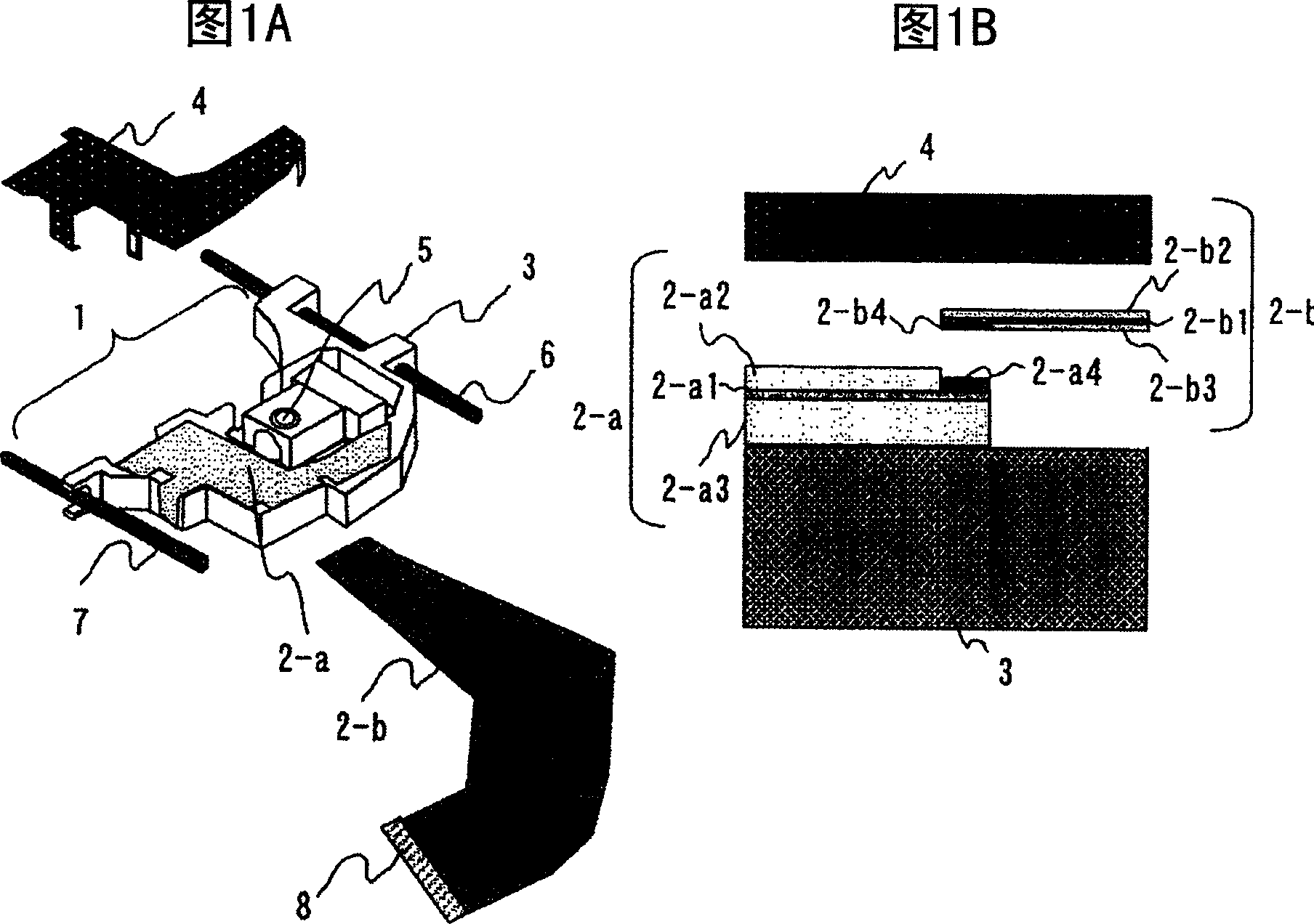
[0065] First, referring to the first embodiment of the method of connecting the first flexible substrate 2-a and the second flexible substrate 2-b according to the present invention Figure 6 Be explained.
[0066] Figure 6 It is a flowchart showing a schematic manufacturing process of the optical pickup device according to the present invention.
[0067] The general manufacturing process of the optical pickup device includes: the step S41 of punching out the flexible substrate from the base material purchased in the form of a sheet; The process S42 of fixing the LSI chip component with a soldering material such as solder paste on a, and then electrically connecting and mounting the LSI chip component to the first flexible substrate 2-a through a reflow operation; The step S43 of soldering and connecting the secondary flexible substrate connecting the light-emitting element or the light-receiving element to the predetermined first flexible substrate 2-a on the pick-up devic...
Embodiment 2
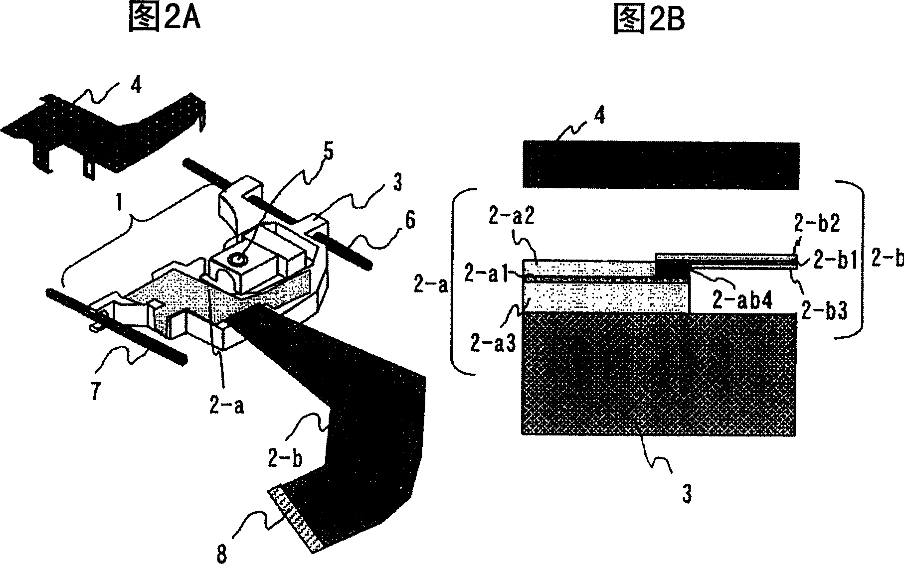
[0080] For the second example of the method of connecting the first flexible substrate 2-a and the second flexible substrate 2-b according to the present invention Figure 8 illustrate. Figure 8 It is a figure which shows 2nd Example. In Embodiment 2, the difference from the first embodiment is that the first flexible substrate 2-a and the second flexible substrate 2-b are connected on opposite sides with respect to the height direction of the optical pickup device, The metal protective cover 4 attached and fixed to the case 3 has a structure in which the first flexible printed circuit 2-a is fixed. Have again, when this structure LSI chip is not installed on the metal protective cover 4 side, and when being installed on the housing 3 side of the optical pickup, if adopting the solder plating of the same side as the installation of the LSI in the connection, because Solder plating only needs to be done on one side, so the cost can be reduced.
Embodiment 3
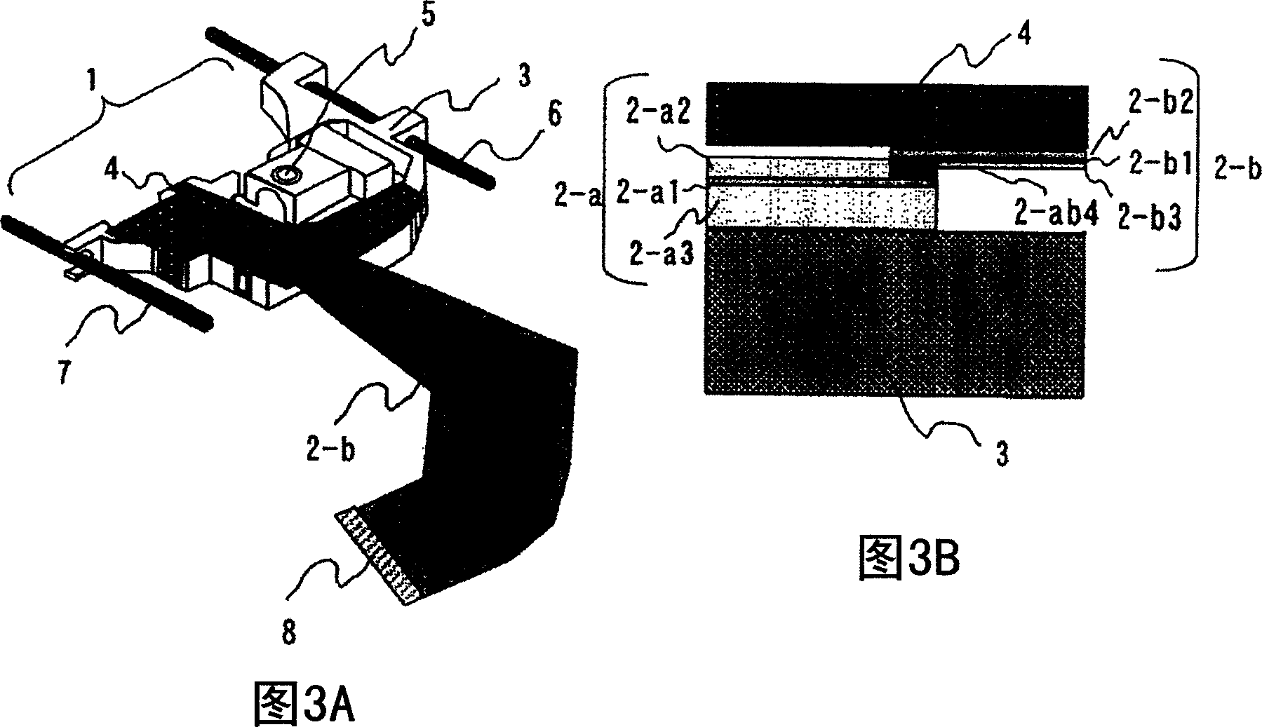
[0082] Next, the method for connecting the first flexible substrate 2-a and the second flexible substrate 2-b according to the present invention will be described for the third embodiment. Figure 9 Be explained. Figure 9 It is a figure which shows 3rd Example. In the third embodiment, the difference from the first and second embodiments is that the connection end is bent in the height direction (vertical direction) of the optical pickup device and overlapped and connected in the horizontal direction, which is used in the housing for the optical pickup The structure in which the vertical part of the lower protective cover 4-1 made of metal installed and fixed on the inner side of 3 is pressed is effective when the restriction in the height direction is severe. Furthermore, in the third embodiment, the connecting end of the first flexible substrate may be bent in advance, and the optical pickup case 3 may be connected to the connecting end of the second flexible substrate by ...
PUM
| Property | Measurement | Unit |
|---|---|---|
| drag | aaaaa | aaaaa |
Abstract
Description
Claims
Application Information
 - R&D
- Intellectual Property
- Life Sciences
- Materials
- Tech Scout
- Unparalleled Data Quality
- Higher Quality Content
- 60% Fewer Hallucinations
Browse by: Latest US Patents, China's latest patents, Technical Efficacy Thesaurus, Application Domain, Technology Topic, Popular Technical Reports.
© 2025 PatSnap. All rights reserved.Legal|Privacy policy|Modern Slavery Act Transparency Statement|Sitemap|About US| Contact US: help@patsnap.com


