Device for fixing an internal magnetic screen to a frame

A magnetic screen and frame technology, applied in the field of color cathode ray tubes, can solve the problems of high material cost, inability to reuse parts, difficulty in automation, etc.

Inactive Publication Date: 2006-09-13
THOMSON LICENSING SA
View PDF0 Cites 2 Cited by
  • Summary
  • Abstract
  • Description
  • Claims
  • Application Information

AI Technical Summary

Problems solved by technology

[0009] The installation method using rivets or welding has the disadvantage that the parts constituting the frame and the screen cannot be reused when a problem occurs with respect to any of ...

Method used


Image

  • Device for fixing an internal magnetic screen to a frame
  • Device for fixing an internal magnetic screen to a frame
  • Device for fixing an internal magnetic screen to a frame

Examples


Embodiment Construction

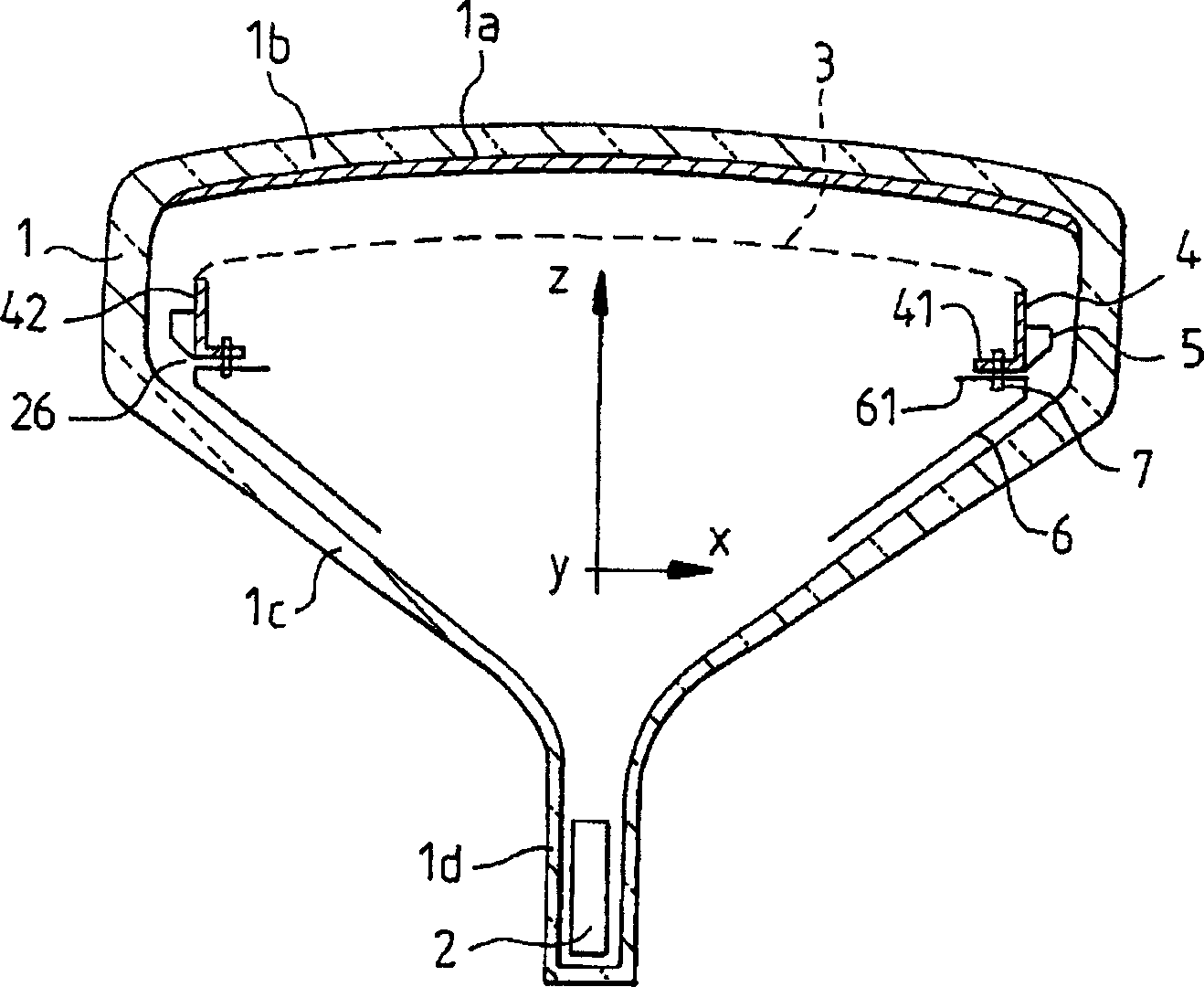
[0020] figure 1 The structure of a color cathode ray tube is shown in cross-section. This kinescope 1 comprises frame / shadow mask assembly, and described frame / shadow mask assembly comprises shadow mask 3, and the curved surface of described shadow mask can be realized by stamping steel plate or invart steel plate, and described surface is arranged at a distance from fluorescent screen 1a. At a certain distance, the phosphor screen is placed on the glass panel 1b of the picture tube; the shadow mask is held in place by a rigid frame 4, to which the shadow mask is connected by welding at its peripheral edge, the The peripheral edge is folded to extend within said frame in a direction substantially parallel to the longitudinal axis Z. The frame itself is rectangular in shape, each side of which has at least partially an L-shaped cross-section, the frame having a side 42 extending in a direction parallel to the longitudinal axis and a flange 41 substantially perpendicular to the...


PUM


Abstract

A cathode ray tube comprising an internal magnetic screen (60) and a frame (40) supporting a shadow mask (3). The screeen is attached to the frame by means of cut-out tabs (63) on the peripheral lip (61) of the screen. The tabs are inserted into openings (62) on the surface of the flange (41) of the frame entering into contact with the screen. Said type of attachment makes it possible to eliminate additional parts and to automatize the attachment of the screen to the frame.

Description

technical field [0001] The present invention relates to a color cathode ray tube having a substantially flat screen, and more particularly to a color selection frame / shadow mask assembly incorporating such a picture tube. [0002] The invention finds application in any type of picture tube comprising a color selection mask, and moreover it is applicable to picture tubes with a shadow mask realized by stamping and to picture tubes with a shadow mask to which it is attached The rigid frame is held in tension within the picture tube. Background technique [0003] Conventional cathode ray tubes consist of a glass envelope within a vacuum. Inside the envelope, the picture tube includes a color selection shadow mask located at a precise distance from the glass panel of the picture tube on which a grid of red, green and blue illuminants is placed to form a phosphor screen. An electron gun is arranged in the rear of the picture tube along the longitudinal axis of the picture tube,...

Claims


Application Information

Patent Timeline
IPC IPC(8): H01J29/06
CPCH01J2229/003H01J29/06H01J29/02
Inventor 佩德罗·科斯马
Owner THOMSON LICENSING SA
Why Eureka
Try Eureka