
Autostereoscopic display apparatus

An autostereoscopic display and display device technology, applied in stereoscopic systems, image communications, electrical components, etc., can solve problems such as the limitation of the properties of spatial light modulators

Active Publication Date: 2006-09-20
AU OPTRONICS CORP
View PDF3 Cites 4 Cited by
  • Summary
  • Abstract
  • Description
  • Claims
  • Application Information

AI Technical Summary

Problems solved by technology

Likewise, there are theoretical constraints on the properties of spatial light modulators

Method used


Image

  • Autostereoscopic display apparatus
  • Autostereoscopic display apparatus
  • Autostereoscopic display apparatus

Examples


Embodiment Construction

[0092] First, several different display devices to which the pixel arrangement of the present invention is applied are described. The pixel arrangement of the present invention may be applied to a display device as described in WO 03 / 015,424, which is hereby incorporated by reference. A few of these kinds of display devices are now outlined, however, other features of display devices are described in WO 03 / 015,424 and may be incorporated in a display device according to the invention.

[0093] First, refer to Figure 7 To describe a 2D / 3D switchable direction display device particularly suitable for realizing the present invention, Figure 7 A switchable orientation display is shown, as described in WO 03 / 015,424.

[0094] Backlight 1034 produces optical output 1036 that is incident on input linear polarizer 1038 and LCD TFT substrate 1040 . Light passes through a pixel plane 1042 comprising an array of LCD pixels 1044-1058. Each pixel includes separate regions of addressa...


PUM


Abstract

An autostereoscopic display apparatus comprises a spatial light modulator comprising an array of pixels arranged in rows and columns in a pixel plane, and a spatially multiplexing parallax element capable of directing light from successive columns of pixels towards successive ones of two or more viewing windows in a nominal window plane. The pixels comprise pixel apertures 546 having gaps 547 therebetween with the gaps between the columns of pixels extending substantially parallel to the columns of pixels. The arrangement of the pixels is designed taking account of the intensity profile of an image of a nominal human pupil in the nominal window plane formed in the pixel plane by the spatially multiplexing parallax element to reduce the amount of spatially derived flicker observed by a viewer moving in the window plane. In one arrangement, the pixel apertures repeat at a pitch equal to a representative width of said intensity profile. In another arrangement, the total height of the pixel apertures parallel to the columns of pixels has a profile which increases towards the edges of the pixel apertures relative to the centre of the pixel apertures.

Description

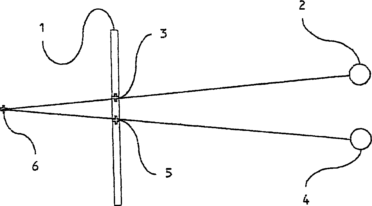
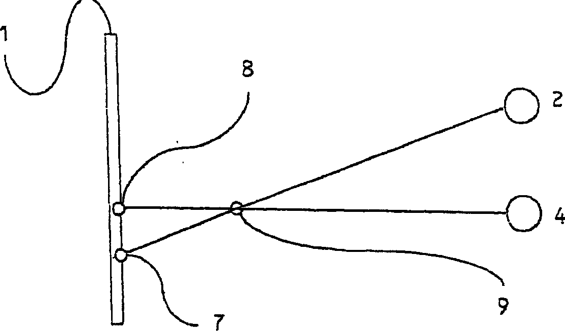
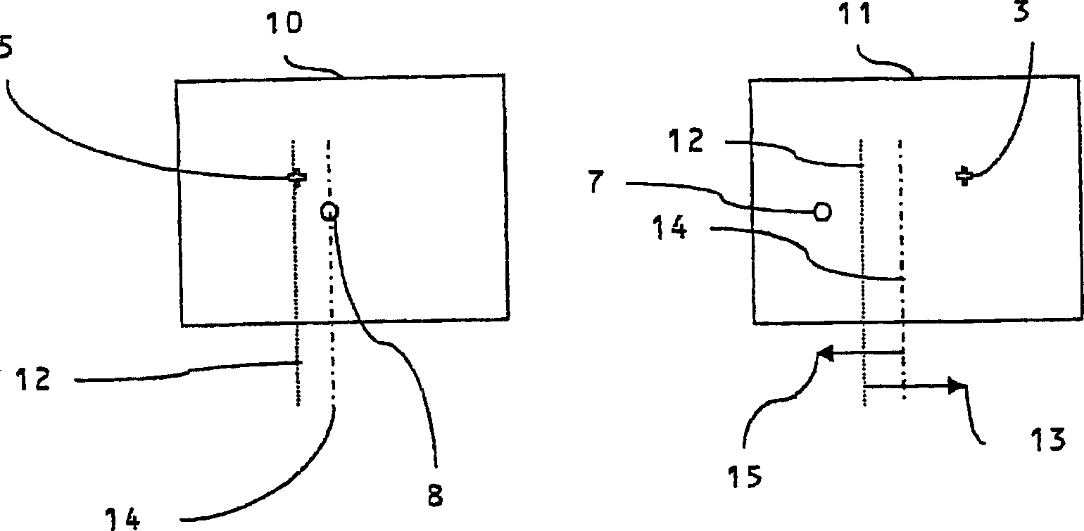
technical field [0001] The invention relates to an autostereoscopic display device. Such a device may be used in a switchable two-dimensional (2D) / three-dimensional (3D) autostereoscopic display device. Such systems can be used in computer monitors, communication handhelds, digital cameras, laptop and desktop computers, gaming devices, automotive and other mobile display applications. Background technique [0002] Normal human vision is stereoscopic, ie, each eye sees a slightly different range of images. The brain merges two images (called a stereo pair) to give a sense of depth. Stereoscopic displays replay to each eye separate images (usually planar) that correspond to what would be seen when viewing a real-world scene. The brain merges the stereo pairs again to give the image the apparent depth. [0003] Figure 1a A plan view of the display surface in display plane 1 is shown. The right eye 2 looks at the right eye homologous image point (homologous image point) 3 ...

Claims


Application Information

Patent Timeline
IPC IPC(8): H04N13/00H04N13/04
CPCH04N13/0404H04N13/0454H04N13/0422H04N13/0409H04N13/305H04N13/31H04N13/324H04N13/359
Inventor 乔纳森·哈罗尔德格雷厄姆·J·伍德盖特
Owner AU OPTRONICS CORP
Learn More