Oil storage device

An oil storage device, oil bag technology, applied in the direction of transmission device, bearing, bearing of linear motion, etc., can solve the problem of uneven and continuous oil supply

Inactive Publication Date: 2006-10-04
HIWIN TECH
View PDF0 Cites 11 Cited by
  • Summary
  • Abstract
  • Description
  • Claims
  • Application Information

AI Technical Summary

Benefits of technology

This new type of oil supply system includes an oil tank where there are two parts: one part called the oil reservoir contains some liquid or solid material like grease (oil) which helps keep the engine running smoothly). Another part called a rubber plug made from synthetic materials allows pressurized air into its interior through holes on top. When compressed by this force, the gas inside goes towards the exterior of the container while keeping any excess fluid behind them. By doing this, the amount of lubricious oily substance remaining within the oil may decrease overtime without affecting how well other components work properly.

Problems solved by technology

Prior technical problem addressed by this patented solution relates to improving the performance of conventional linear transmission assemblies (LTRAs) containing lubricant systems like Linear Sliders and Ball Screws. These designs use external oily tank arrangements which may lead to insufficiently stored lubricants leading to excessive wear on these parts over their lifetime. Additionally, there exist other challenges related to maintaining sufficient lubricity during operation despite having no accessory equipment attached inside them.

Method used


Image

  • Oil storage device
  • Oil storage device
  • Oil storage device

Examples


Embodiment Construction

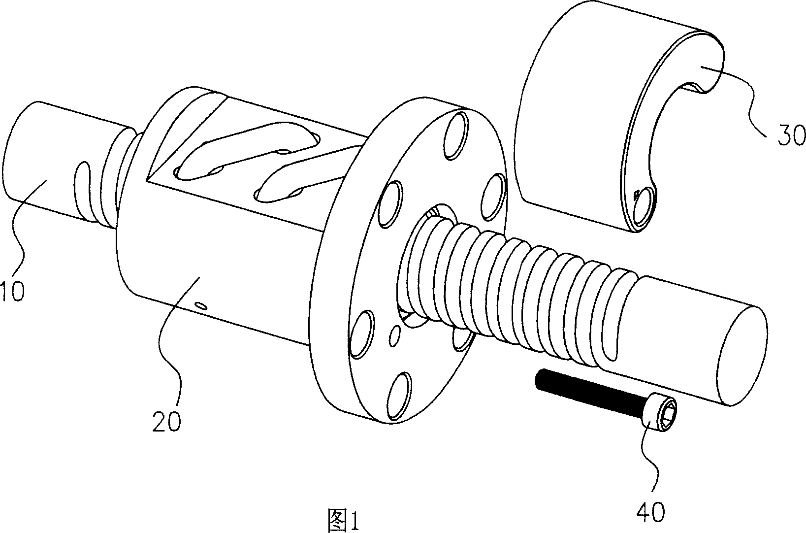
[0040] 1 is a schematic diagram of the application of the oil storage device of the present invention to a ball screw; the ball screw is mainly composed of a screw shaft 10 fitted with a nut 20, and the rolling body in the nut 20 is used to roll Therein, the screw shaft 10 and the nut 20 can move relative to each other. In this embodiment, the oil storage device 30 is disposed on the end surface of the nut 20 ; the oil storage device 30 is fixed on the nut 20 by the oil passage bolt 40 .

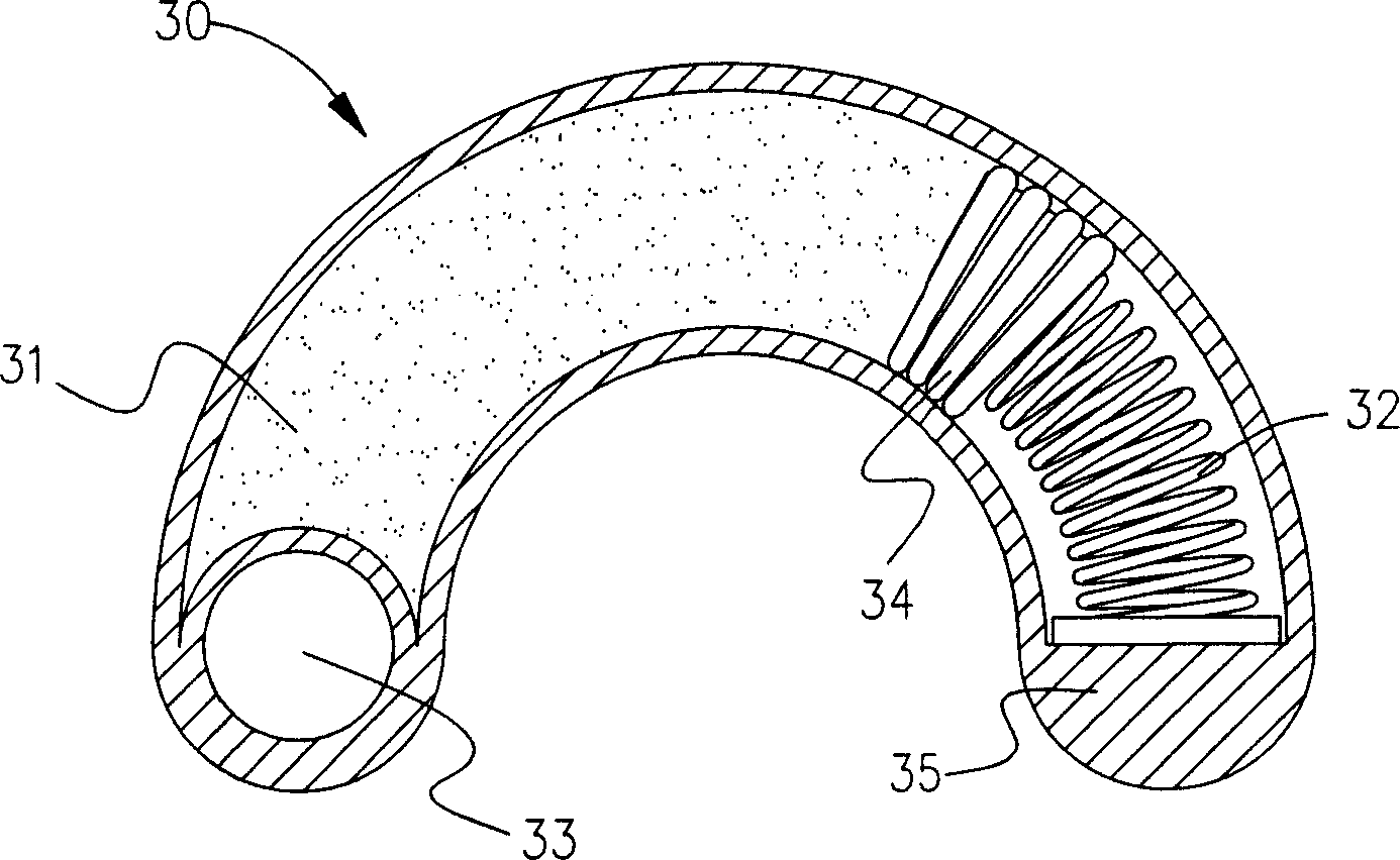
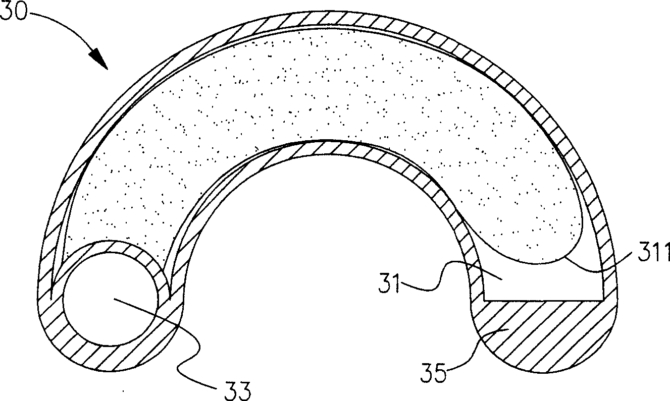
[0041] figure 2 It is a schematic cross-sectional view of the first embodiment of the oil storage device in FIG. 1; wherein the oil storage body 35 of the oil storage device 30 has an oil storage space 31 inside to store lubricating oil; and the oil storage body 35 is also provided with an oil through hole 33, The lubricating oil in the oil storage space 31 can be output outward; the elastic body in the oil storage space 31 of the oil storage device 30 in this embodiment is a structure in w...


PUM


Abstract

The invention discloses an oil-reserving device for lubricating oil, which contains oil-injecting structure, which outputs lubricating oil to the oil-reserving space; the elastic body is set in the oil-reserving space, which can squeeze the lubricating oil to the space automatically.

Description


Claims


Application Information

Patent Timeline
Owner HIWIN TECH
Why Eureka
Try Eureka