LED heat conducting seat and manufacture procedure thereof

A technology of LED lamps and heat pipes, applied in lighting and heating equipment, semiconductor devices of light-emitting elements, cooling/heating devices of lighting devices, etc., can solve the problems of difficult installation, low heat conduction efficiency, etc. The effect of high rate and simple processing procedure

Active Publication Date: 2011-06-15
LI HONG SCI & TECH
View PDF0 Cites 1 Cited by
  • Summary
  • Abstract
  • Description
  • Claims
  • Application Information

AI Technical Summary

Problems solved by technology

[0005] The technical problem to be solved by the present invention is to overcome the disadvantages that the heat conduction efficiency may be low due to poor contact or virtual connection between the existing LED lamp and the heat conduction element, and the disadvantage that the LED lamp needs to install the heat conduction element on the printed circuit board, resulting in difficult installation. Based on years of rich practical experience and professional knowledge engaged in the design and manufacture of such products, the inventor actively researches and innovates in conjunction with the application of theories, in order to create a revolutionary LED heat transfer seat. The main purpose of the present invention is to hope that through this design, Provide an LED heat conduction structure superior to common LED heat conduction structures

Method used


Image

  • LED heat conducting seat and manufacture procedure thereof
  • LED heat conducting seat and manufacture procedure thereof
  • LED heat conducting seat and manufacture procedure thereof

Examples


Embodiment Construction

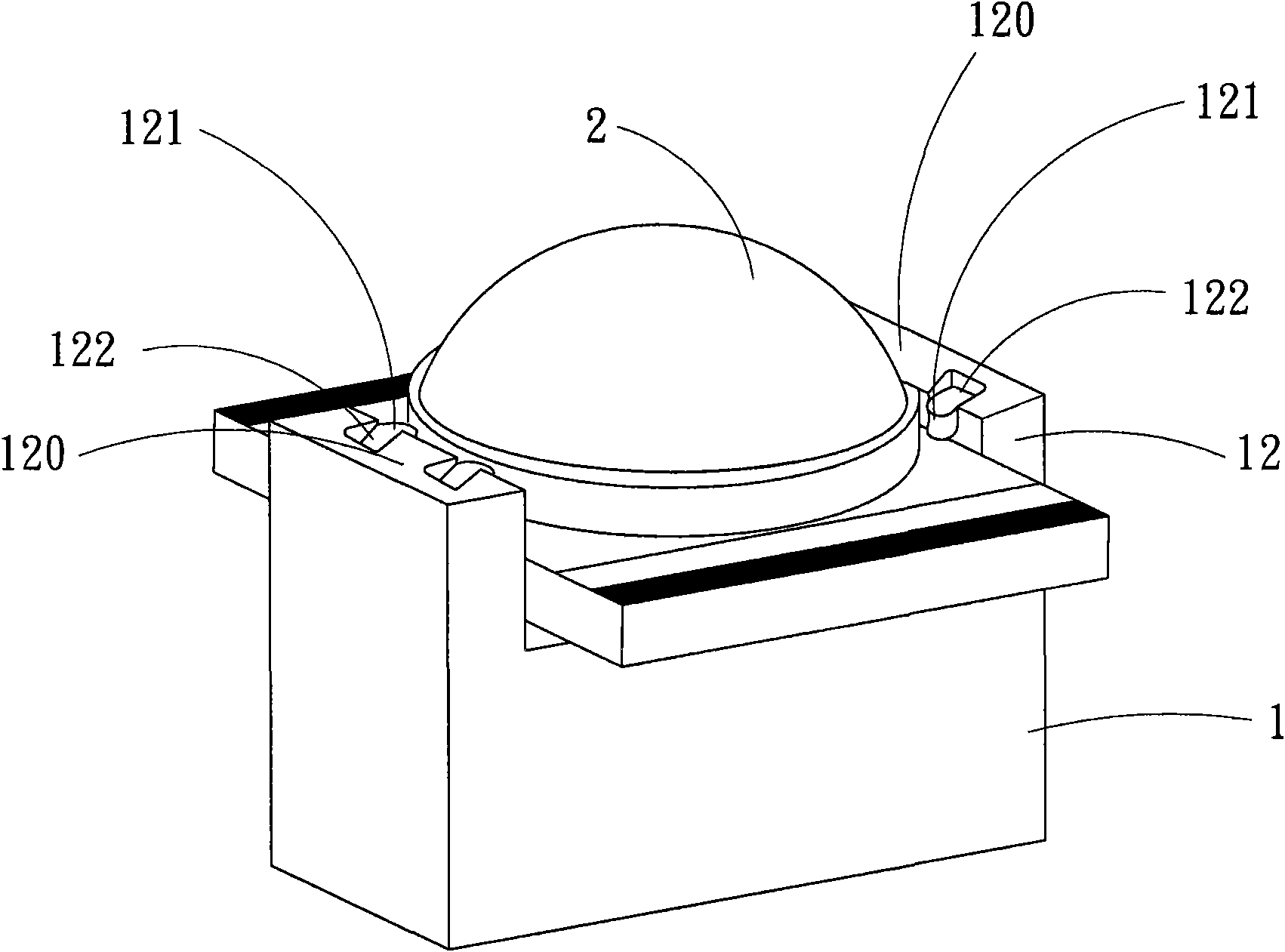
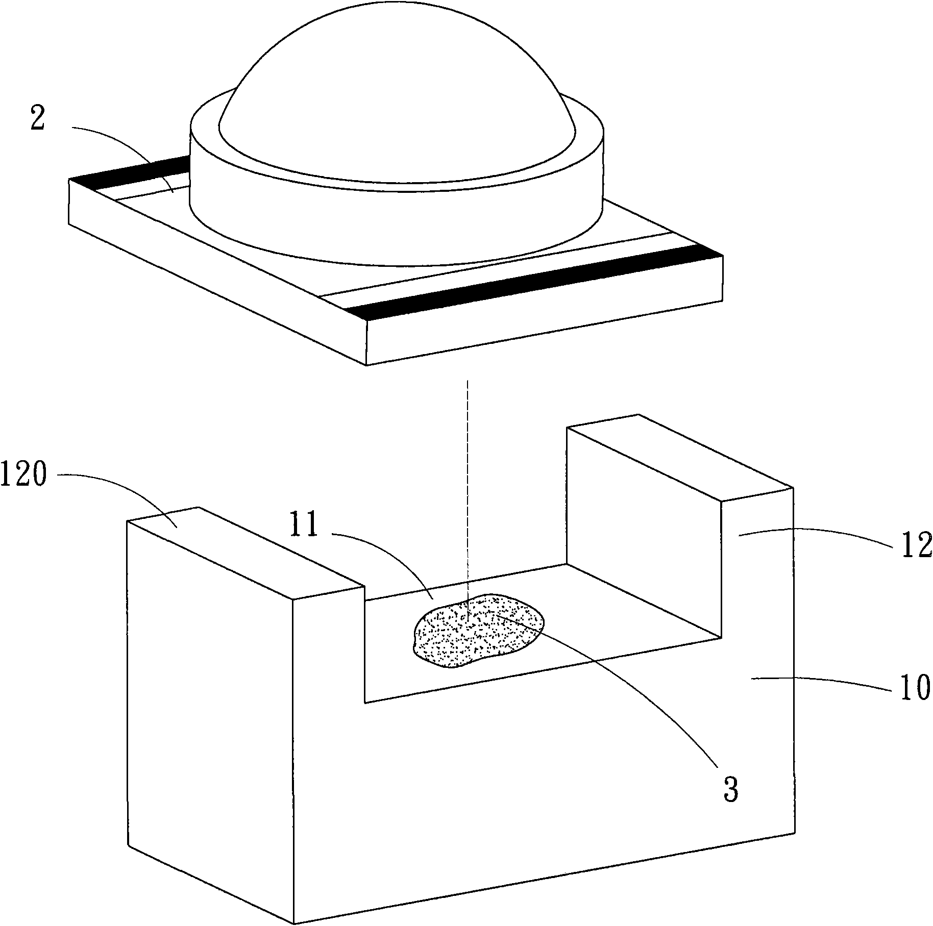
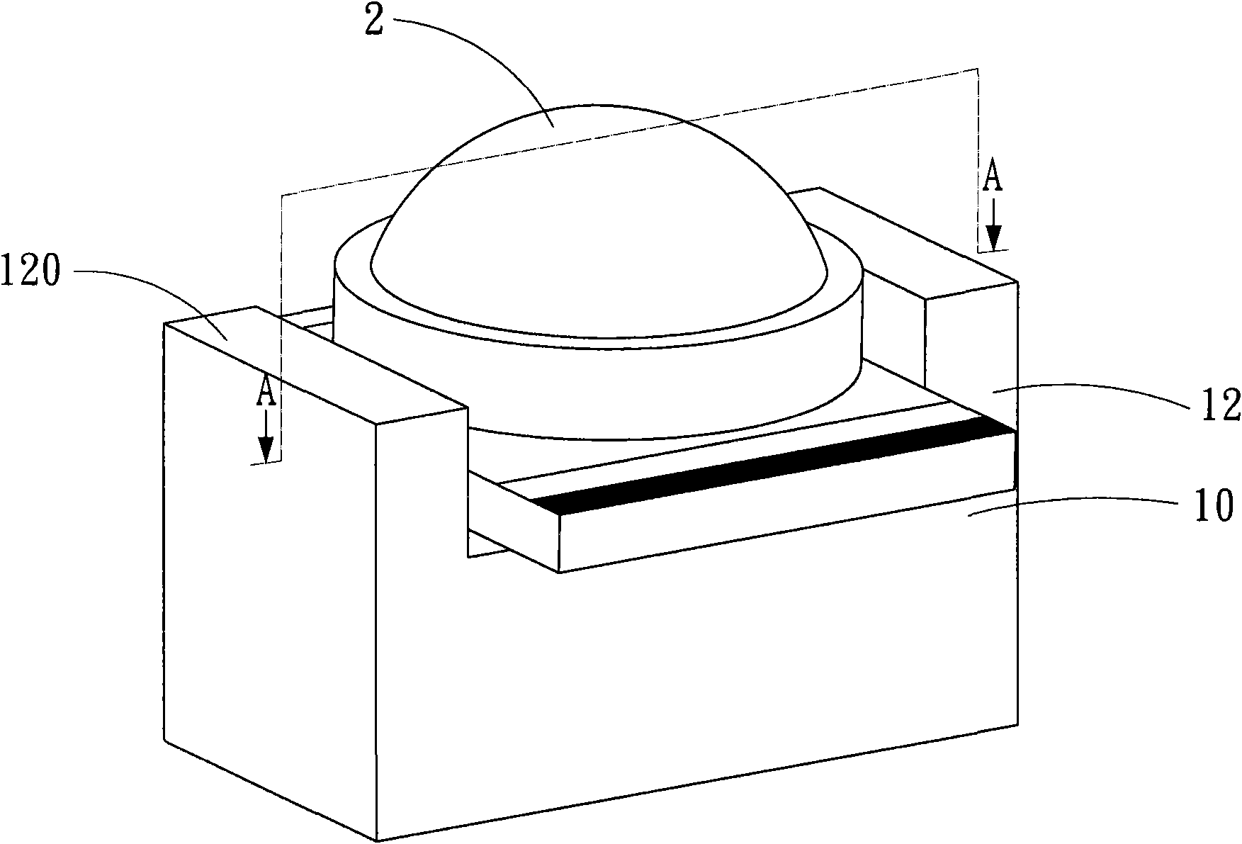
[0027] refer to figure 1 and figure 2 As shown, a kind of LED heat conduction seat 1 is to place the LED lamp 2 on the heat conduction seat prototype 10 (such as figure 2 As shown), the heat transfer seat 1 is provided with a placement area 11, and one or more fixing parts 12 are in the form of blocks or cylinders and are arranged on the periphery of the placement area 11 and are higher than the placement area 11. , the side of the fixing portion close to the placement area 11 is provided with a hooking portion 121 , and the hooking portion 121 faces the placement area 11 and buckles downward.

[0028] refer to Figure 2 to Figure 6 As shown, the placement area 11 of the LED heat transfer seat 1 of the present invention is used to carry the LED lamp 2, the LED lamp 2 is prevented from sliding through the fixing part 12 around the placement area 11, and the placement area 11 near the fixing part 12 One side of the LED lamp 2 is provided with a buckle 121 to buckle down the...


PUM


Abstract

The invention relates to an LED heat conducting seat and a manufacture procedure thereof. The heat conducting seat is provided with a placement area, wherein the periphery of the placement area is provided with one or more fixed parts which are higher than the placement area; a compressing area is arranged on the fixed part; the compressing area on the fixed part is obliquely extruded by a die sothat materials of the fixed part are extruded from inner part to the upper part of the placement area to form a hooking part; and an LED lamp can be forcedly pressed and buckled in the placement area, the LED lamp can be tightly attached to the heat conducting seat, the effect of forced heat conduction is achieved, and the temperature of the LED lamp can be rapidly reduced.

Description

technical field [0001] The invention relates to an LED heat conduction seat and a manufacturing process thereof, in particular to an LED heat conduction seat with both fixing and forced heat conduction functions and a manufacturing method thereof. Background technique [0002] Commonly used LED lamps are equipped with a heat conducting part at the bottom of the LED chip. When the LED lamp is used for lighting, the heat generated can be transferred by the bottom heat conducting part to reduce the temperature of the LED lamp. [0003] However, the commonly used LED lamps and their heat-conducting parts are only set in contact with each other. In actual use, sometimes there will be poor contact or false connection, and the higher the brightness of the LED lamp, the more heat it will generate. For lamps such as traffic lights that combine multiple LED lights to form the lighting surface or marking surface, if the LED lights overheat due to poor heat conduction, it will not only ...

Claims


Application Information

Patent Timeline
Patent Type & Authority Applications(China)
IPC IPC(8): F21V19/00F21Y101/02F21V29/00F21V29/50F21V29/83F21Y103/10F21Y107/40F21Y115/10
Inventor 阮庆源张昆荣林国俊阮庆煌
Owner LI HONG SCI & TECH
Why Eureka
Try Eureka