
Fin antenna device of automobile radio

An antenna device and radio technology, applied to antennas, antennas suitable for movable objects, electrical components, etc., can solve the problems of flat antennas not receiving signals, occupying space, and unsatisfactory radio reception of helical antennas, etc.

Inactive Publication Date: 2006-10-04
YEOUJYI ELECTROINCS
View PDF0 Cites 11 Cited by
  • Summary
  • Abstract
  • Description
  • Claims
  • Application Information

AI Technical Summary

Problems solved by technology

[0002] By the way, due to the advancement of radio technology, many products are gradually becoming wireless. The most troublesome thing in radio technology is the design of the antenna. The antenna is related to the frequency, direction and intensity of the radio wave. Generally, the design of the antenna is based on the radio wave. To calculate 1 / 4λ, a long metal rod shape with a certain length is designed, which takes up a lot of space. Therefore, the AM and FM antennas on the car are designed to be long rod-shaped telescopic, and AM and FM share one antenna. It is stretched out when it is closed and retracted when it is closed. However, after a long time of use, it will fail and cannot be retracted, which is quite inconvenient.
[0003] Therefore, some companies have developed a helical antenna, which bends a long metal rod into a helical shape, but the radio reception of the helical antenna is not ideal, so there is a so-called glass antenna design, which is attached to the car glass with a soft conductive material This kind of glass antenna is also an antenna design shared by AM and FM, but the material is quite expensive
There are also many planar antennas that use a special curvature on the printed circuit board. This kind of planar antenna has a big disadvantage that it cannot be close to substances with metal surfaces, because metal will absorb radio waves, and the car shell is metal. so that the planar antenna cannot receive the signal

Method used


Image

  • Fin antenna device of automobile radio
  • Fin antenna device of automobile radio
  • Fin antenna device of automobile radio

Examples


Embodiment Construction

[0026] In order to enable your review committee to further understand the technology, means and effects of the present invention to achieve the intended purpose, please refer to the following detailed description and accompanying drawings of the present invention. It is believed that the purpose, characteristics and characteristics of the present invention can be obtained from this To gain a deep and specific understanding, the attached drawings are only for reference and illustration, and are not intended to limit the present invention.

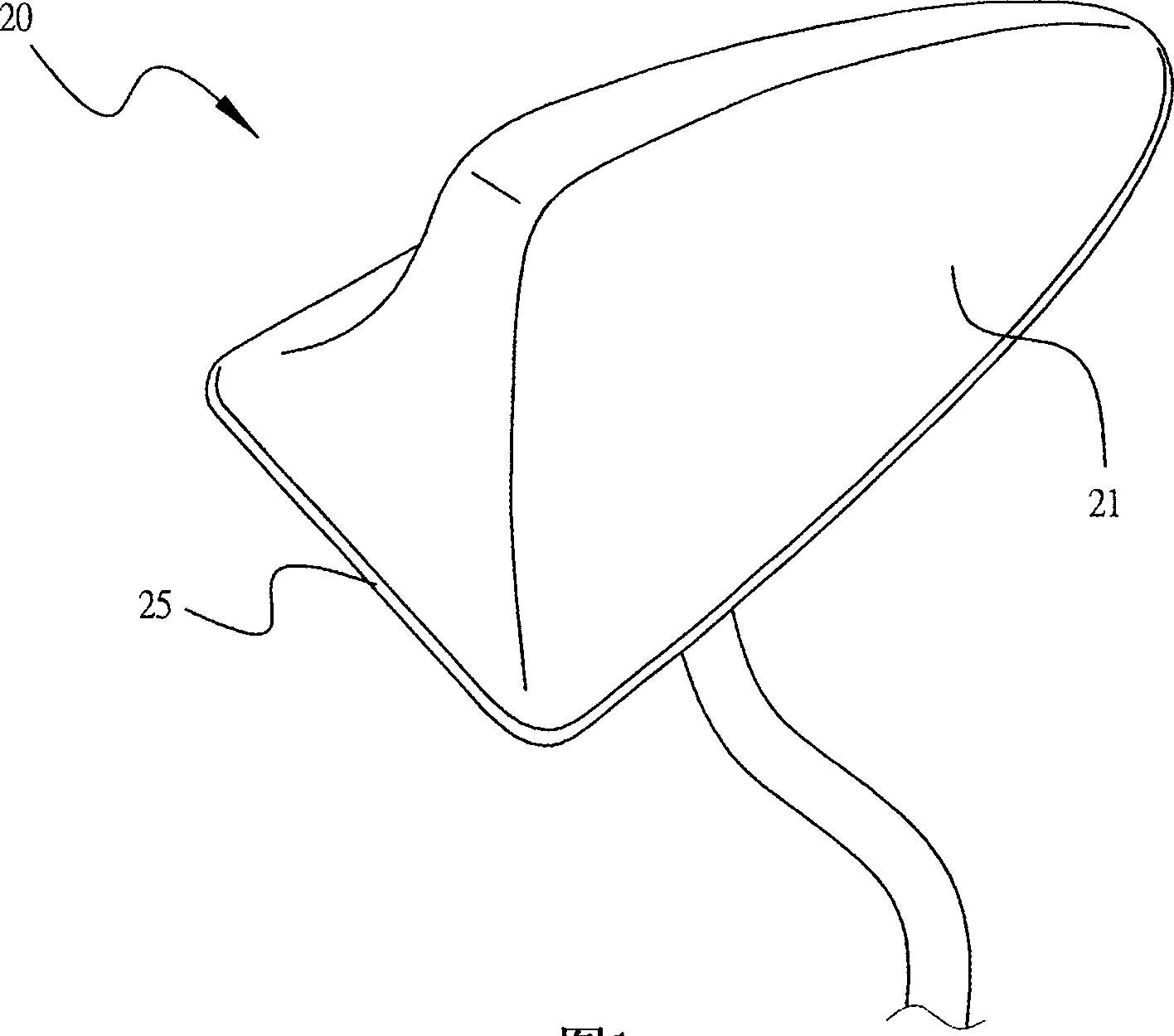
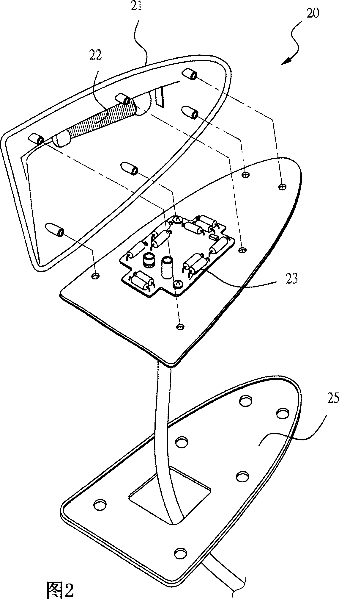
[0027] See first figure 1 As shown, it is an external perspective view of an embodiment of the car radio fin antenna of the present invention, and Fig. 2 is the figure 1 In the three-dimensional exploded view, the fin antenna device 20 of the present invention can be mainly used before the radio receiving circuit of a car radio to receive a radio frequency band signal of a radio. like figure 1 , the shape of the fin antenna device 20 resem...


PUM


Abstract

The invention relates to a manch type antenna device of a car radio which is used to receive at least one wireless electric band signal before it is connected with a wireless electric receiving circuit. It comprises a manch type external cover, an AM antenna, a signal amplifying circuit plate, a FM vibrator antenna circuit positioned on the signal amplifying circuit plate and a mental base, wherein the AM antenna and the FM vibrator antenna circuit are designed separately; the FM vibrator antenna circuit uses a plurality of inducers to form the vibrator circuit and can connect the mental base to reinforce the signal receiving ability of the FM vibrator antenna circuit.

Description

technical field [0001] The invention relates to a fin antenna device for a car radio, in particular to a fin antenna device used on a car AM / FM radio, which can be installed on the roof of the car and has a receiving antenna for enhancing the radio frequency signal of the radio device. Background technique [0002] By the way, due to the advancement of radio technology, many products are gradually becoming wireless. The most troublesome thing in radio technology is the design of the antenna. The antenna is related to the frequency, direction and intensity of the radio wave. Generally, the design of the antenna is based on the radio wave. To calculate 1 / 4λ, a long metal rod shape with a certain length is designed, which takes up a lot of space. Therefore, the AM and FM antennas on the car are designed to be long rod-shaped telescopic, and AM and FM share one antenna. It stretches out when it is closed, and retracts when it is closed. However, after a long time of use, it wil...

Claims


Application Information

Patent Timeline
IPC IPC(8): H01Q1/32H01Q23/00
Inventor 吕裕盛
Owner YEOUJYI ELECTROINCS
Learn More