Motor

A motor and wire technology, which is applied in the field of small motors, can solve the problems of difficult wire hooking, poor wire hooking accuracy, poor connection, etc., and achieves the effect of eliminating poor welding and good hooking.

Inactive Publication Date: 2010-12-15
COPAL CO LTD
View PDF6 Cites 0 Cited by
  • Summary
  • Abstract
  • Description
  • Claims
  • Application Information

AI Technical Summary

Problems solved by technology

In contrast, in a small motor, if the number of turns of the coil is increased, the flange must be formed in a special Y-shape. Since the shape of the flange is formed in a special shape, it is difficult for the wire to be caught in the The cut-in part of the commutator piece, as a result, the hooking accuracy of the wire relative to the cut-in part deteriorates, and when the wire is brazed to the commutator piece, there may be poor connection

Method used


Image

  • Motor
  • Motor
  • Motor

Examples


Embodiment Construction

[0028] Hereinafter, preferred embodiments of the motor of the present invention will be described in detail with reference to the accompanying drawings.

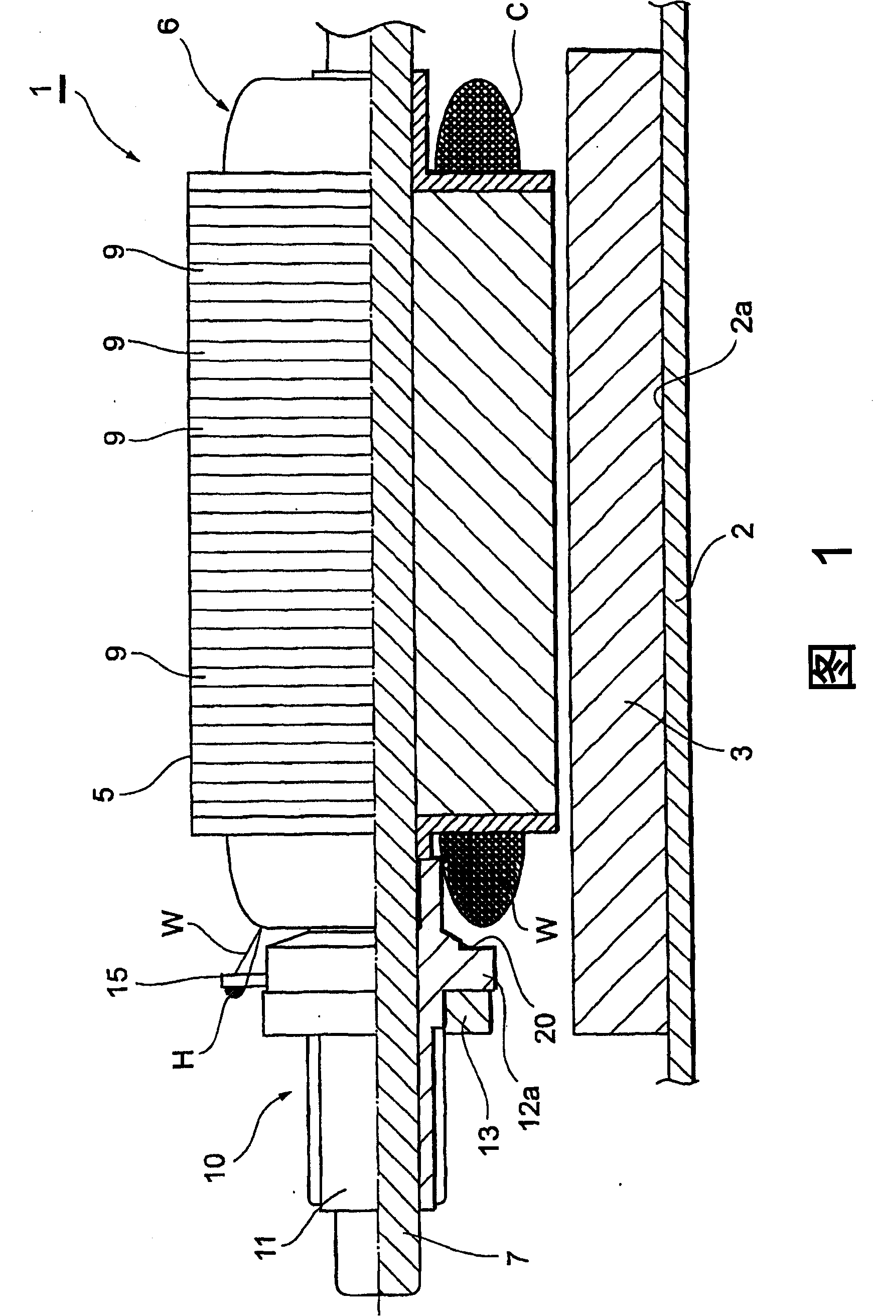
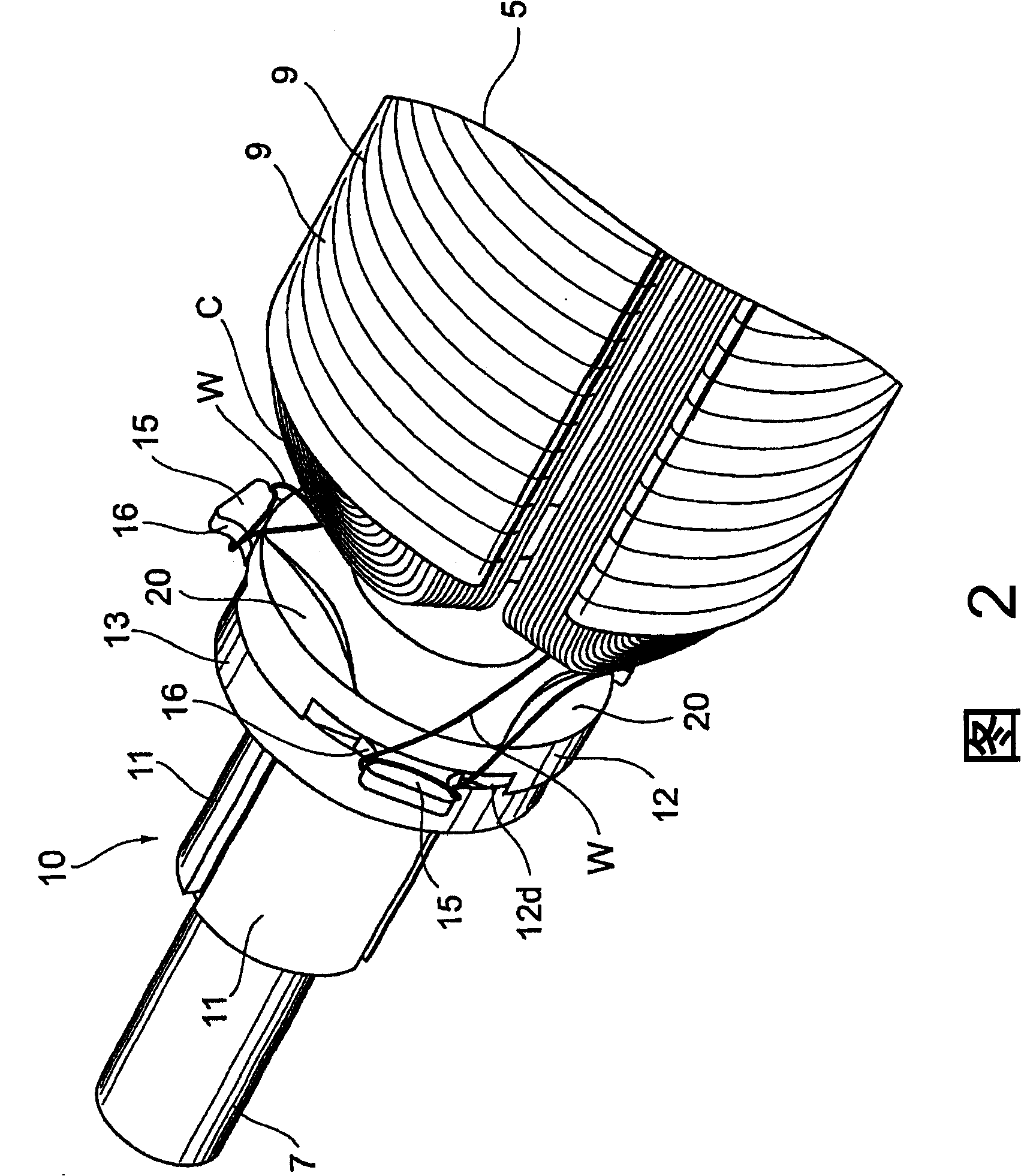
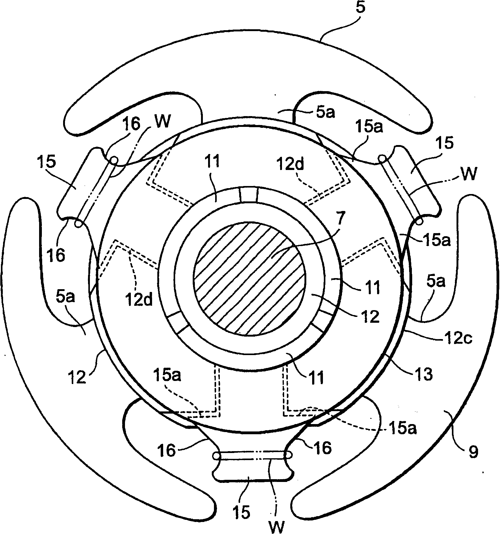
[0029] Such as Figure 1 ~ Figure 3 As shown, the motor 1 is composed of a tubular motor, and has a cylindrical metal casing 2, and a resin bracket (not shown) for assembling a pair of brushes is fixed to the rear end of the casing 2. The motor 1 is a small motor, and the housing 2 has a cylindrical shape with a diameter of 10 mm or less (for example, 6 to 3 mm) and a length of about 1 cm. A stator 3 and a rotor 6 are accommodated in the small housing 2 .

[0030] A stator (magnet) 3 made of permanent magnets having N and S poles is fixed on the inner wall surface 2a of the casing 2, and a rotor 6 is accommodated inside the casing 2. The rotor 6 has a coil C, and the wire W of the coil C It is wound on the pole 5a of the core 5 having three core slots (slots). In addition, the iron core 5 of the rotor 6 is formed by lamina...


PUM


Abstract

In a motor (1), applying a sleeve (12) with circular flange (12a) to block well the wire hang and entrance part (16) of wire (W) opposite to the commutator (11) and prevent badness in welding the (W) on (11), which reduces gap between iron core (5) and flange (12a) and is harmful to coil (C) winding number; thereby, on axis of shaft (7), arranging a rabbet (20) on flange (12a) opposite to the coil.

Description

(1) Technical field [0001] The present invention relates to a small electric motor, and more particularly to an electric motor having a commutator for reversing the current flowing through the rotor coils. (2) Background technology [0002] Conventionally, there is Japanese Patent Application Laid-Open No. 9-117109 as a technology in this field. The commutator described in this gazette is configured such that a commutator segment made of a thin metal plate is mounted in a resin bushing, and the vertical segment portions of the commutator segments protrude from the flange portion of the bushing. In addition, the flange portion of the bushing has a circular or special Y-shaped shape, and in either case, the flange portion can reinforce the vertical piece portion of the commutator segment. [0003] Patent Document 1: Japanese Patent Laid-Open No. 9-117109 [0004] Patent Document 2: Japanese Patent Laid-Open No. 10-271769 [0005] In a motor, it is necessary to increase the ...

Claims


Application Information

Patent Timeline
Patent Type & Authority Patents(China)
IPC IPC(8): H02K13/04H01R39/04
CPCH01R39/04H02K1/185H02K1/26H02K13/006
Inventor 高桥厚德武田芳正
Owner COPAL CO LTD
Why Eureka
Try Eureka