Sealing structure for battery and battery employing sealing structure for battery

A battery and sealing technology, used in battery pack parts, circuits, electrical components, etc., can solve the problems of spot welding operability limitations, low battery current collection, poor discharge characteristics, etc., to eliminate poor welding and increase electrical conductivity. The effect of improving the area and current collection

Active Publication Date: 2016-01-06
PANASONIC ENERGY WUXI
View PDF5 Cites 0 Cited by
  • Summary
  • Abstract
  • Description
  • Claims
  • Application Information

AI Technical Summary

Problems solved by technology

In actual production, the positive plate 105 sometimes has a burr at the edge, that is, the above-mentioned end, so that when the battery group is formed as described above, the burr will scratch or pierce the spacer 107, thereby causing a short circuit between the positive and negative electrodes.
[0007] And, carry out the spot welding of battery lead wire 103 and sealing plate 102 under the state that battery pack is packed into casing 101, because the length of battery lead wire 103 is generally short, thereby cause the workability of this spot welding to be limited, sometimes Will lead to false welding
[0008] In addition, as mentioned above, since the spot welding area of ​​one end of the battery lead 103 to the foamed nickel substrate is small, the battery has low current collection performance and poor discharge characteristics when the battery is in use.

Method used


Image

  • Sealing structure for battery and battery employing sealing structure for battery
  • Sealing structure for battery and battery employing sealing structure for battery
  • Sealing structure for battery and battery employing sealing structure for battery

Examples


Embodiment Construction

[0063] Specific embodiments of the present invention will be described below using the drawings.

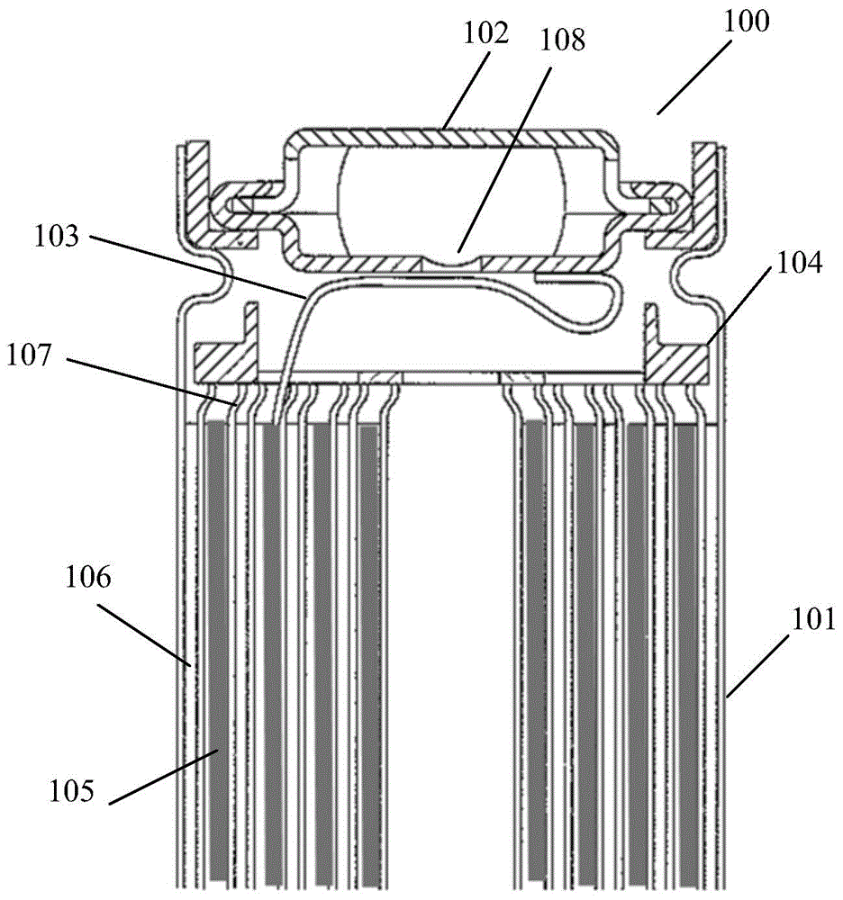
[0064] In this embodiment, if Figure 4 As shown in , the schematic structure of the battery 10 of the present invention is shown.

[0065] The battery 10 will be described as an example where the battery 10 is a cylindrical nickel metal hydride battery. The battery 10 has a positive plate 15; a negative plate 16 is spaced apart from the positive plate 15; a spacer 17 is arranged between the positive plate 15 and the negative plate 16 to insulate the positive plate 15 and the negative plate 16; one end ( Figure 4 The upper end of the middle) opening, containing the positive plate 15, the negative plate 16 and the spacer 17; the insulating sheet 20, arranged on the opening of the housing 11; and the sealing member 19, arranged on the insulating sheet 20, sealing the housing 11 , and is electrically connected to the positive plate 15, including the sealing plate 12 and the spri...


PUM


Abstract

The invention provides a sealing structure for a battery and the battery employing the sealing structure for the battery. The sealing structure for the battery comprises a sealing plate and a connection part, wherein the sealing plate is used for sealing a battery shell; the connection part is used for electrically connecting a battery positive plate and the sealing plate; the connection part comprises a spring body and a current collector; the current collector is connected with the spring body; the spring body contacts the sealing plate; and the current collector contacts the battery positive plate.

Description

technical field [0001] The present invention relates to a sealing structure for a battery that reduces defects in processing with a positive electrode plate and reduces defects in spot welding between a lead wire and a sealing plate, and a battery using the sealing structure for a battery. Background technique [0002] In recent years, personal computers, mobile phones, personal digital assistants (PDAs) and other information electronic equipment and audio-visual electronic equipment are rapidly becoming smaller, lighter, and cordless. improve. Therefore, various studies have been conducted on performances such as safety and stability of batteries. [0003] For cylindrical nickel-metal hydride batteries, the battery group serving as the internal electrodes of the battery is generally formed as follows: figure 1 as well as image 3 As shown, firstly prepare a strip-shaped positive electrode plate 105 formed by laminating the electrode plate and the foamed nickel substrate,...

Claims


Application Information

Patent Timeline
Patent Type & Authority Applications(China)
IPC IPC(8): H01M2/02H01M2/26H01M2/34H01M50/107H01M50/536H01M50/59
CPCY02E60/10
Inventor 安未明叶兰倪霞李超马天行
Owner PANASONIC ENERGY WUXI
Why Eureka
Try Eureka