
Cavity type phase shifter

A phase shifter and cavity-type technology, which is applied to waveguide devices, electrical components, circuits, etc., can solve the problems of high processing cost, unbalanced support of the feed point of the RF circuit board, and influence on electrical performance, so as to avoid passive The hidden danger of intermodulation, the simple machining boundary, and the effect of preventing the influence of thermal deformation

Inactive Publication Date: 2021-03-02
GUANGDONG BROADRADIO COMM TECH
View PDF7 Cites 0 Cited by
  • Summary
  • Abstract
  • Description
  • Claims
  • Application Information

AI Technical Summary

Problems solved by technology

There are also some defects in this patent solution: firstly, regardless of the inclination angle between the axis of the first through hole and the longitudinal direction of the cavity, the transmission cable will inevitably be bent, which is easy to cause stress on the solder joint of the cable outer conductor and form intermodulation hidden danger; secondly, the first through hole is arranged on the wiring groove with uneven shape, which is difficult to process and the processing cost is relatively high, and because of the large number of slots penetrating into the interior, it is easy to cause mechanical damage in the cavity where the radio frequency line is located. The burr remains, forming a hidden danger of intermodulation; again, the setting of the wiring groove also limits the wiring of the transmission cable outside the phase shifter. The transmission cable can only be routed in the horizontal plane where the wiring groove is located. In order to avoid the too small bending radius of the transmission cable When the antenna is bent, enough space needs to be reserved between the phase shifters, which often limits the realization of further miniaturization of the antenna width; finally, the sliding medium needs to be loaded into the cavity with the radio frequency circuit before the outer conductor of the transmission cable is welded In the body, due to the high temperature generated by the soldering operation, there is a hidden danger of thermal deformation of the sliding medium, which affects the electrical performance and increases the friction of the medium sliding, which affects the realization of the phase shifter phase adjustment function.
[0004] In order to fix the radio frequency circuit board or the insulating support of the radio frequency circuit board, there are card slots on the left and right package walls in the cavity built in the phase shifter cavity. The structures on both sides of the card slot are asymmetrical, resulting in two The side support is unbalanced, and the circuit board is easily deformed when the feed point is welded, resulting in poor welding or internal stress concentration at the feed point, which seriously affects the stability of the electrical performance of the phase shifter
In addition, in the engineering practice of aluminum alloy extrusion or broaching, the height of the slot is limited and should not be too small. This also puts forward special requirements for the selection of the thickness of the RF circuit board, which limits the impact of the cavity on The adaptability of the basic thickness of the RF circuit is not conducive to the reduction of the overall cost of the phase shifter
In addition, the insufficient stability of the radio frequency circuit in the built-in space of the cavity is also not conducive to the automatic welding operation of the phase shifter components

Method used


Image

  • Cavity type phase shifter
  • Cavity type phase shifter
  • Cavity type phase shifter

Examples


Embodiment 1

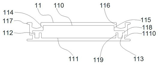
[0069] Please refer to figure 1 , figure 2 with Figure 4 , The phase shifter cavity of the present invention includes a cavity body 11, a radio frequency circuit 12 built in the cavity, and a sliding medium 13 attached to the radio frequency circuit and sliding on its surface. In order to better explain the structure and principle of the present invention, the present invention also discloses the transmission cable 14 assembled with the phase shifter cavity, and other embodiments can also be described by the transmission cable.

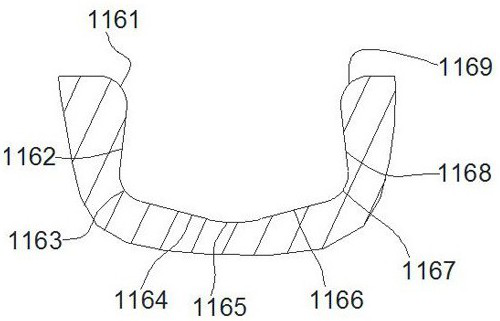
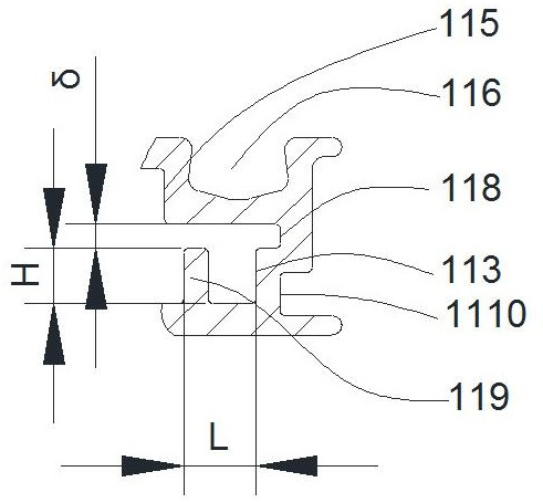
[0070]The cavity 11 is integrally formed by aluminum alloy extrusion or broaching, and the cavity has six packaging walls (upper packaging wall 110, lower packaging wall 111, first left packaging wall 112, first Right packaging wall 113, second left packaging wall 114, second right packaging wall 115). The package wall defines a cavity (not numbered) for accommodating the radio frequency circuit board and other related components (such as sliding...

Embodiment 2

[0079] Please refer to Image 6 , Figure 7 The cavity-type phase shifter of the present invention is a four-port phase shifter, including a cavity 21 , a radio frequency circuit 22 disposed in the cavity 21 , and a sliding medium 23 between the cavity 21 and the radio frequency circuit 22 .

[0080] The cavity 21 is integrally formed by aluminum alloy extrusion or broaching, and there are cavities (210, 211) arranged in layers along the upper and lower packaging walls that penetrate the cavity 21 along the longitudinal direction. . The same radio frequency circuit 22 can be set in the upper cavity 210 and the lower cavity 211, so that the four-port phase shifter is suitable for single-frequency dual-polarization antennas; it can also be provided with different circuit radio frequency circuits 22, so that the phase shifter is suitable for for multi-frequency antennas.

[0081] At least one pair of tongues 2111 are provided on the outside of the cavity 21 on four left and ri...


PUM


Abstract

The invention provides a cavity phase shifter. Wiring grooves are formed in a cavity packaging wall parallel to a radio frequency circuit board, and a plurality of wiring grooves can be formed in different packaging walls; the inner conductor of the transmission cable is in tin soldering connection with the radio frequency circuit through the operation hole formed in the wiring groove, so that thethermal deformation influence on the sliding medium caused by high temperature during tin soldering of the outer conductor of the transmission cable is avoided; the inner sides, opposite to the wiring grooves, of the packaging walls are provided with supporting ribs, thereby increasing the supporting points for the radio frequency circuit board, avoiding the deformation of the radio frequency circuit board during the welding operation, eliminating the deformation of the circuit board during welding and the poor welding or the concentration of the internal stress of a welding spot, and providing a guarantee for the stability of the electrical performance of the phase shifter; and meanwhile, the efficiency of automatic welding operation can be improved. Moreover, by controlling the positions and the heights of the supporting ribs, the phase shifter can adapt to the thicknesses of different radio frequency circuit boards, the flexibility of radio frequency circuit design is improved, andthe cost of the phase shifter can be further reduced.

Description

technical field [0001] The invention relates to the technical field of wireless communication, in particular to a cavity type phase shifter. Background technique [0002] In the coverage of mobile communication network, the electronically adjustable antenna is one of the key equipment of the coverage network, and the phase shifter is the core component of the electronically adjustable antenna. The performance of the phase shifter directly determines the performance of the electronically adjustable antenna, which in turn affects the Therefore, the importance of phase shifters in the field of mobile base station antennas is self-evident. Most of the mainstream phase shifters are developed using the scheme of "cavity + radio frequency line + sliding medium attached to the upper and lower surfaces of the radio frequency line". The signal output by the phase shifter forms a continuous linear phase difference, thereby achieving the purpose of adjusting the downtilt angle through ...

Claims


Application Information

Patent Timeline
Patent Type & Authority Applications(China)
IPC IPC(8): H01P1/18
CPCH01P1/18
Inventor 吴壁群孙丹张鹏
Owner GUANGDONG BROADRADIO COMM TECH
Learn More