Rotary-piston engine

A piston engine, rotary motion technology, used in rotary piston engines, swinging piston engines, rotating or swinging piston engines, etc., to solve problems such as no engine, cylinder heads no longer available for use with ignition rods or spark plugs , to achieve the effect of variable displacement and simple adjustment

Inactive Publication Date: 2006-11-22
赫伯特·许特林
View PDF1 Cites 1 Cited by
  • Summary
  • Abstract
  • Description
  • Claims
  • Application Information

AI Technical Summary

Problems solved by technology

For this reason attempts have been made to make the cylinder head removable, but this has the disadvantage that the cylinder head is no longer available for receiving ignition rods

Method used


Image

  • Rotary-piston engine
  • Rotary-piston engine
  • Rotary-piston engine

Examples


Embodiment Construction

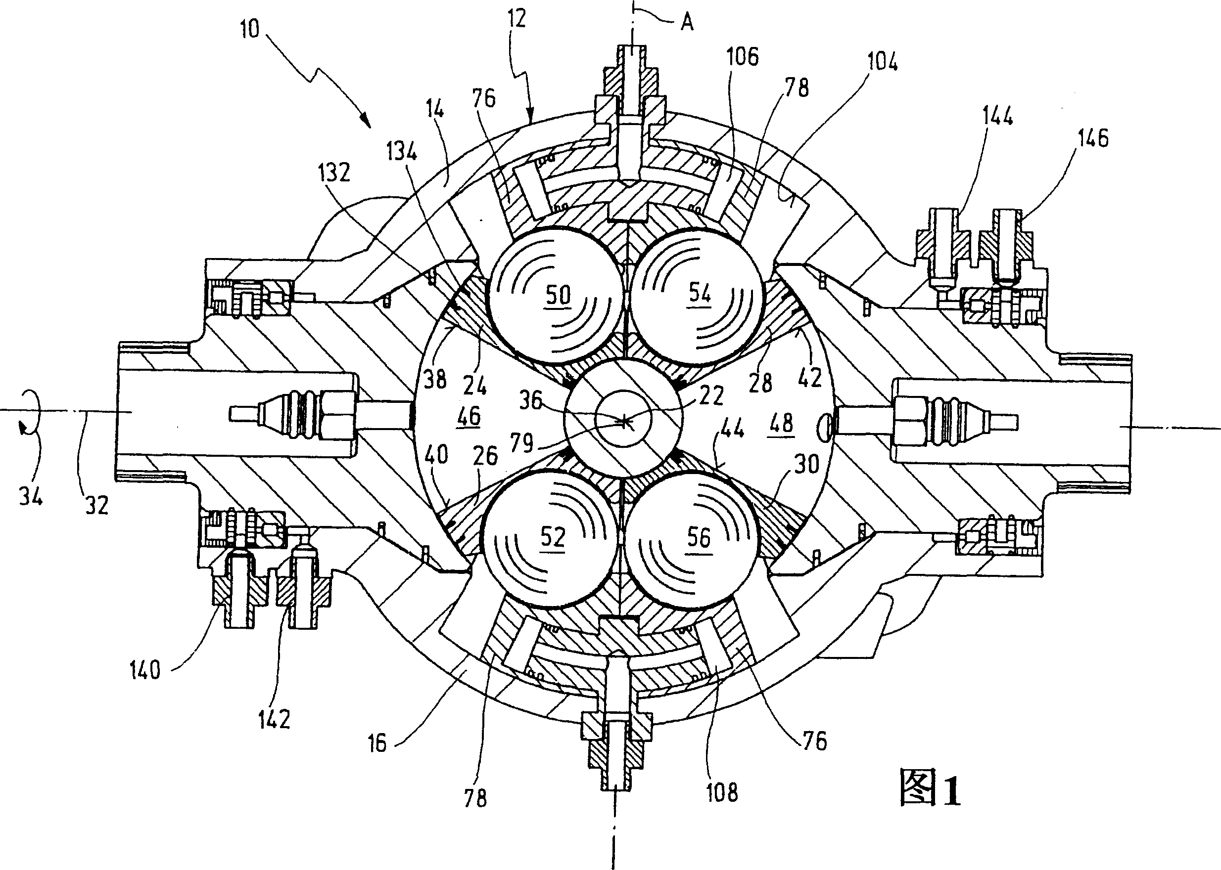
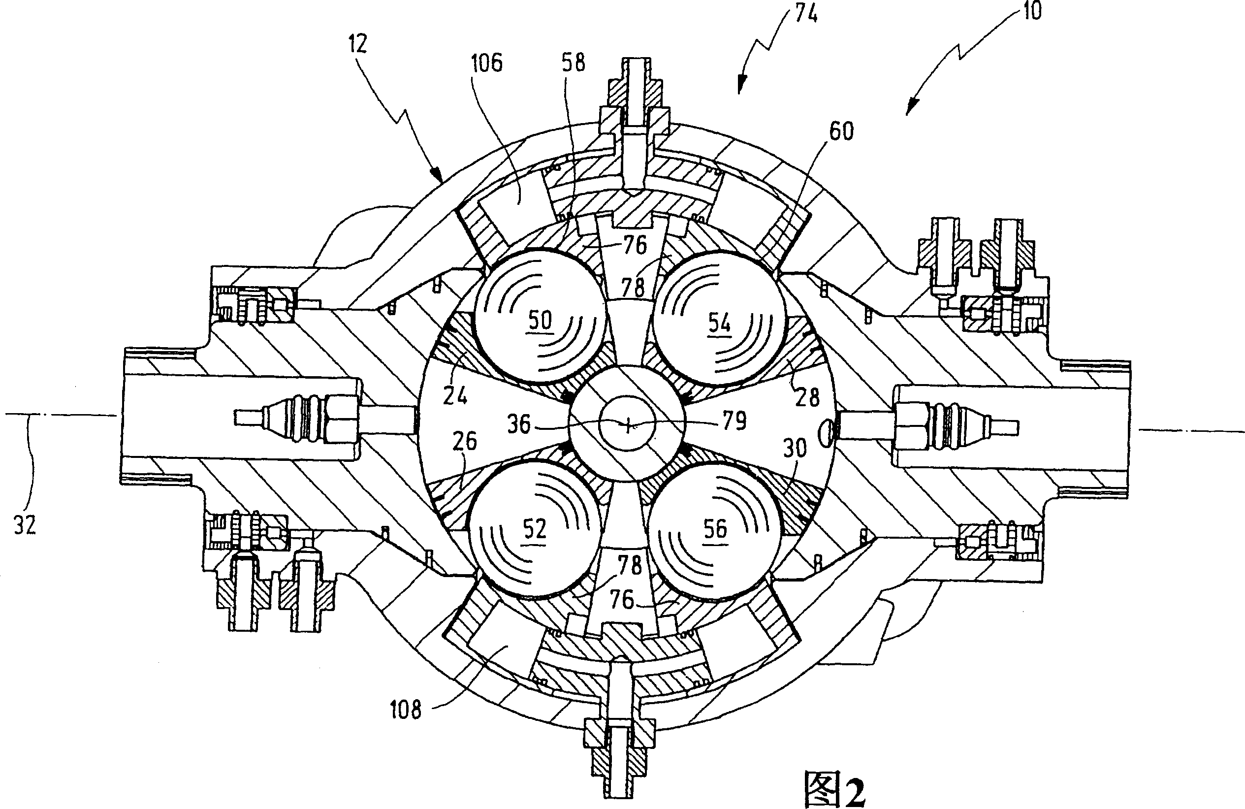
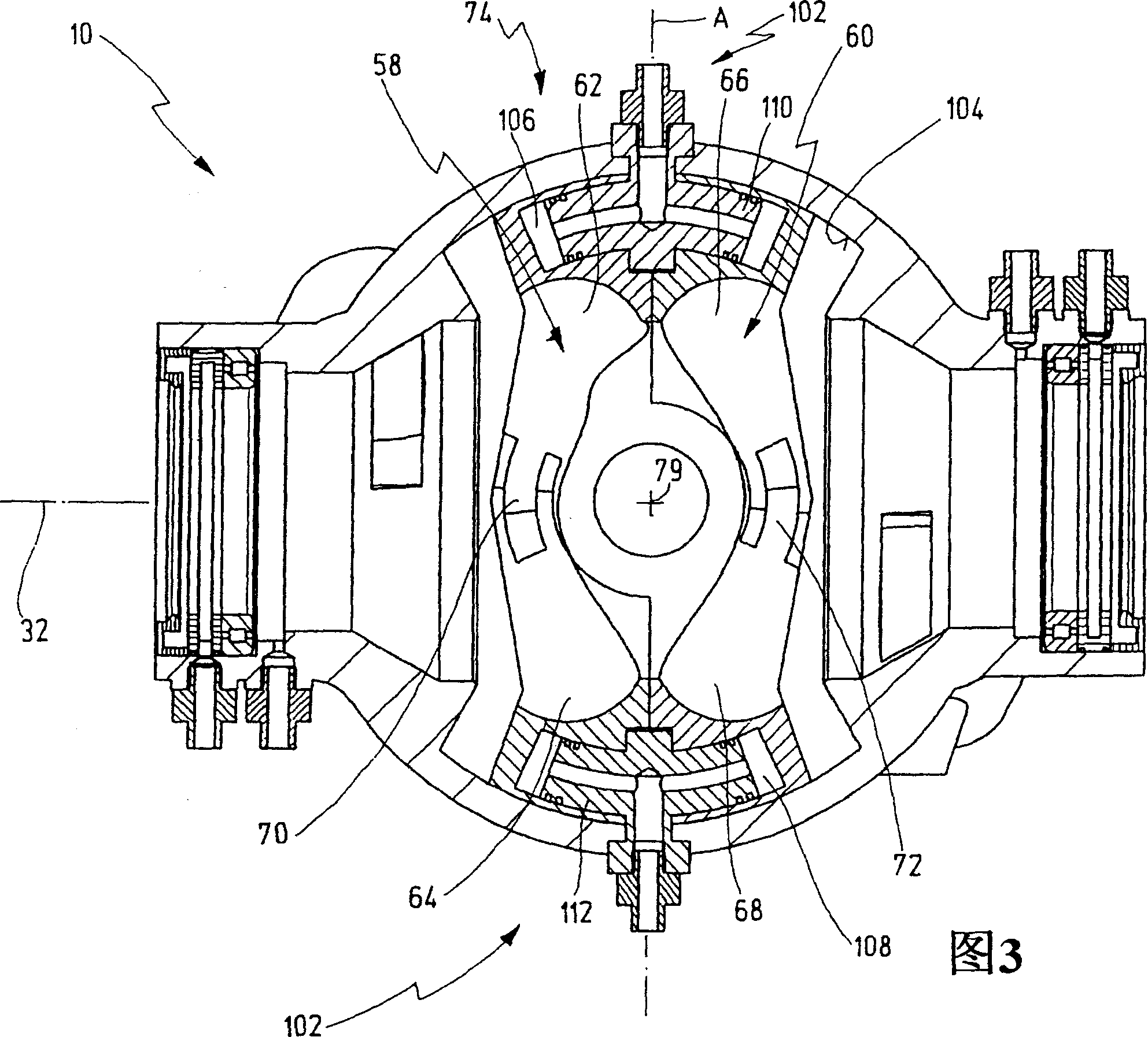
[0060] Figures 1-3 and Figures 6-8 show a rotary piston engine with common reference numeral 10 in different views. 4 and 5 show further details of the rotary piston engine 10 .

[0061] The rotary piston engine 10 is designed as an internal combustion engine in the present exemplary embodiment.

[0062] The rotary piston engine 10 has a housing 12 consisting of two housing parts 14 and 16 . The housing parts 14 and 16 each have a flange, of which only the flange 18 of the housing part 14 is shown in the figures. In the flange there are a large number of holes 20a-20h for passing bolts in order to bolt the two housing parts 14 and 16 to each other via the flange.

[0063] The interior of the shell is spherical or spherically symmetrical, wherein the center point of the ball is marked with reference numeral 22 in FIG. 1 .

[0064] Inside the housing 12 are arranged four pistons 24 , 26 , 28 and 30 . Pistons 24 - 30 are rotatable in housing 12 together around a housing-fixed...


PUM


Abstract

A rotary piston engine having a casing (12) in which are arranged a first and at least one second piston (24, 26), which are capable of encircling a casing-fixed axis of rotation (32) within the casing (12) Rotation, and when they rotate around the axis of rotation (32), around the axis of rotation (36) fixed to the piston perpendicular to the axis of rotation and distributed through the center of the housing, between the first end position and the second end position in opposite directions to each other back and forth rotary motion, wherein the first and at least second piston (24, 26) define a working chamber (48), wherein the first piston (24) and/or the at least second piston (26) have at least one operating mechanism (50, 52), the mechanism is guided along at least one control cam (58) as the first and/or second piston (24, 26) rotates to produce the first and/or at least second piston (24, 26) rotary motion. The control cam (58) is positionally adjustable by means of an adjusting mechanism (74) to adjust at least one of the first and second end positions of at least one of the first and second pistons (24, 26).

Description

technical field [0001] The invention relates to a rotary piston engine having a casing in which a first and at least one second piston are arranged, inside the casing they are jointly rotatable around a casing fixed axis of rotation, and when they rotate around the axis of rotation , around a fixed axis of rotation perpendicular to the axis of rotation and distributed through the center of the housing between a first end position and a second end position in opposite directions to and fro, wherein the first and at least second pistons define a working chamber, wherein the first piston and / or at least the second piston has at least one operating mechanism which is guided along at least one control cam when the first and / or second piston rotates to generate the first and / or at least the second piston Rotary motion of the two pistons. Background technique [0002] Such a rotary piston engine is known from document WO 03 / 067033 A1. [0003] The rotary piston engine and in part...

Claims


Application Information

Patent Timeline
IPC IPC(8): F01C3/02F01C9/00
CPCF01C20/18F04C9/005
Inventor 赫伯特·许特林
Owner 赫伯特·许特林
Why Eureka
Try Eureka