
Link operating device

A technology of linkage device and braking mechanism, applied in mechanical control device, device to prevent/restrict/recover the movement of parts of control mechanism, manual control mechanism, etc., can solve the problem of low rigidity and increase the size of parallel linkage mechanism , the operation device is cumbersome, etc.

Inactive Publication Date: 2006-12-13
NTN CORP
View PDF1 Cites 17 Cited by
  • Summary
  • Abstract
  • Description
  • Claims
  • Application Information

AI Technical Summary

Problems solved by technology

[0005] On the other hand, if the operating range of the moving plate needs to be increased, since each link has a relatively small operating angle range, the links have to be lengthened, which increases the size of the parallel link mechanism and makes the entire operating device bulkier
Also, because of the low rigidity of the mechanism, the weight of the tool carried on the mobile plate, that is, the load capacity of the mobile plate has to be limited to a small range

Method used


Image

  • Link operating device
  • Link operating device
  • Link operating device

Examples


Embodiment Construction

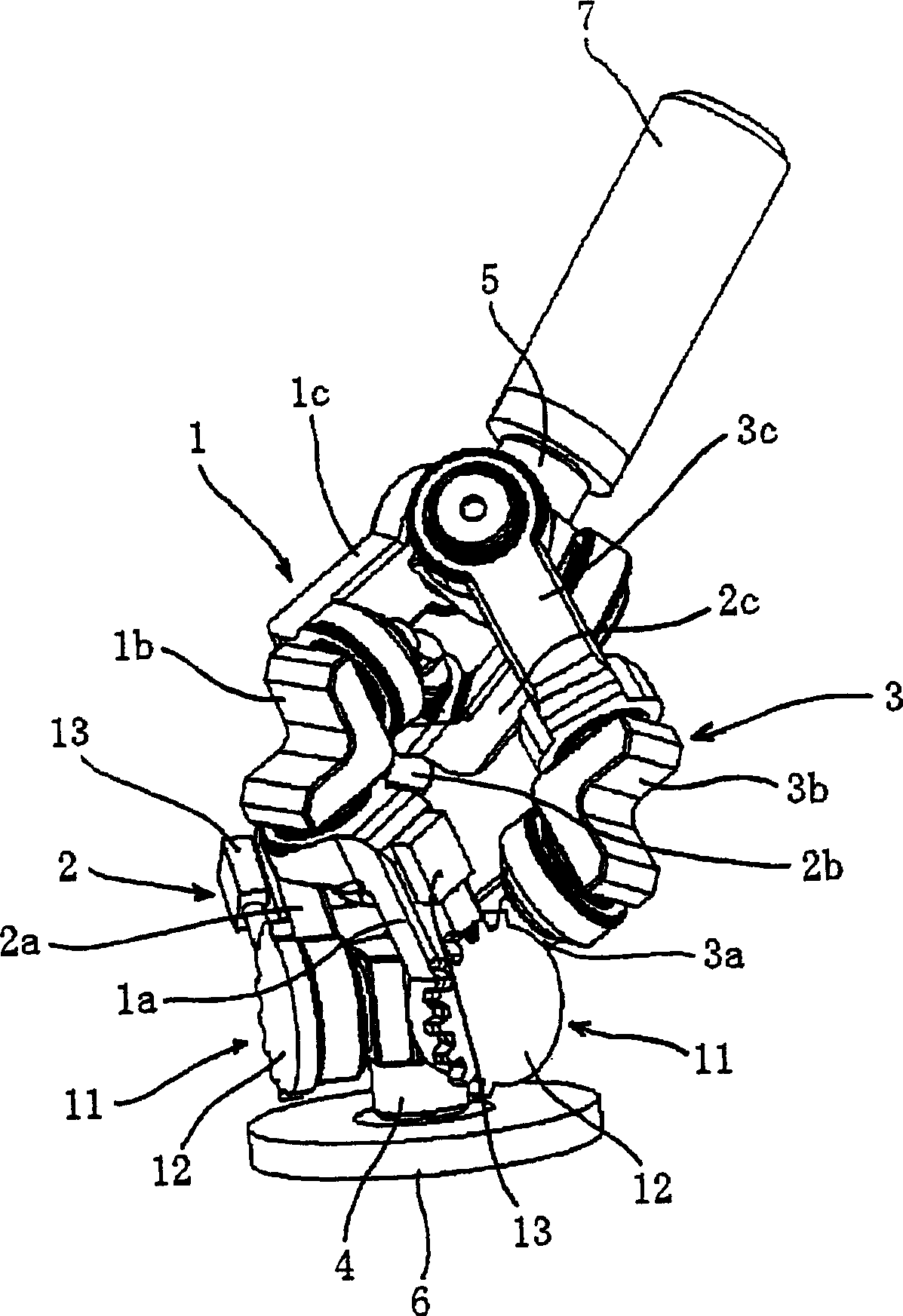
[0023] figure 1 The illustrated embodiment includes three sets of linkages 1-3 used, for example, as parallel linkages or robotic joints to perform complex machining or handling of items in three dimensions with high speed and high precision. .

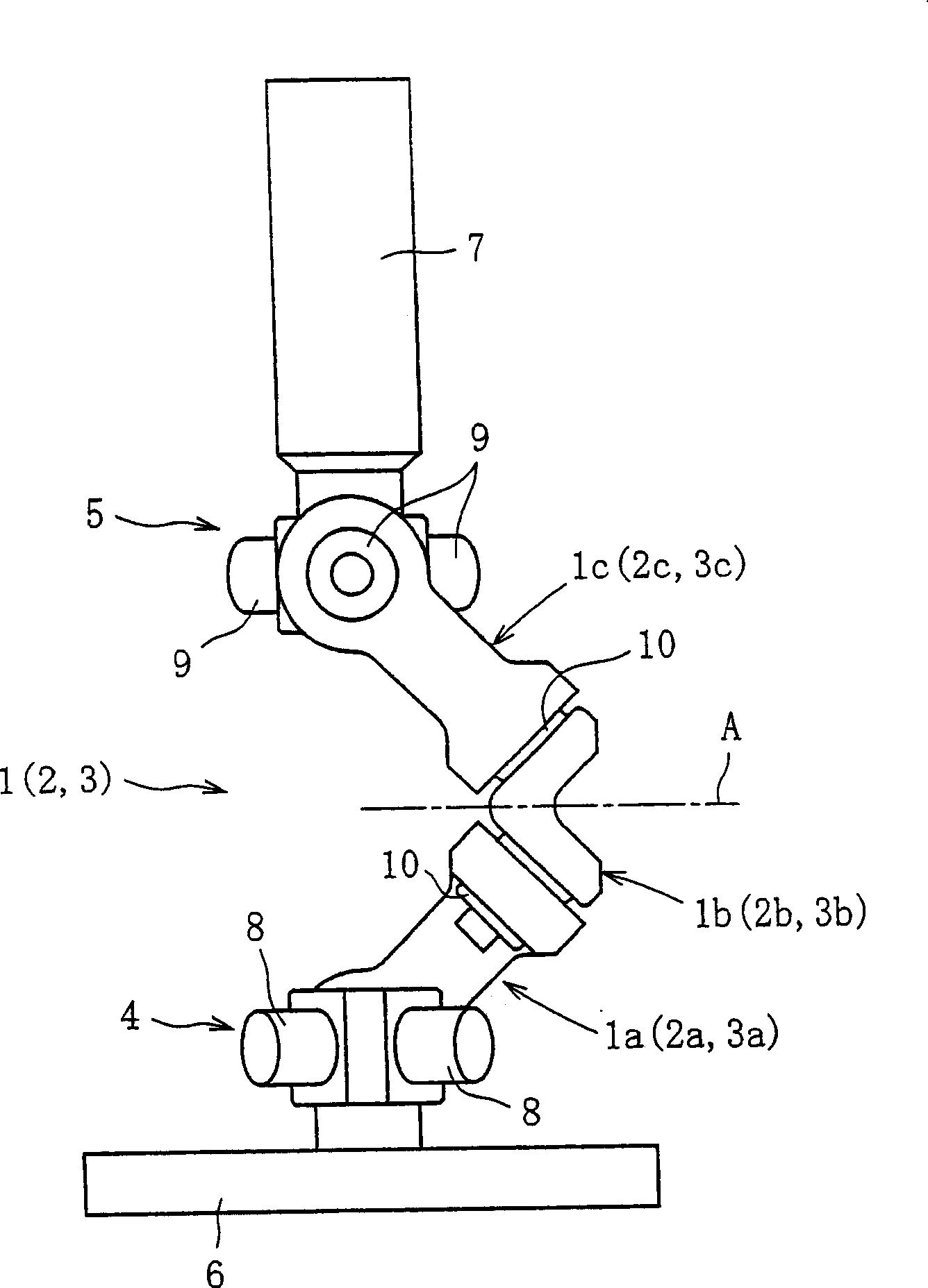
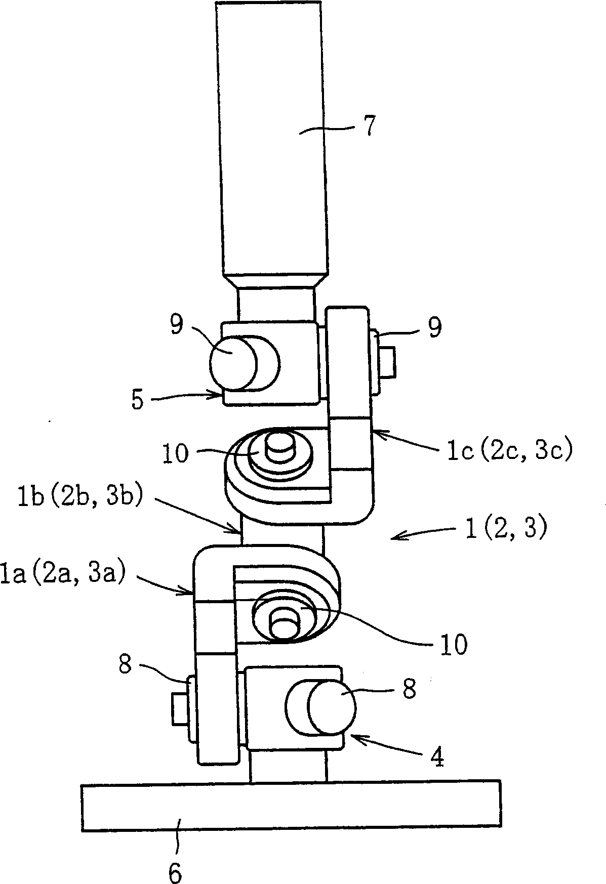
[0024] The input member 6 and the output member 7 are connected together by three sets of linkage mechanisms 1-3 (first to third linkage mechanisms), each of which has a geometrically identical shape. The input part 6 is mounted on an input-side part of the device in which the operating device is incorporated, wherein said input-side part is, for example, a stationary part. The output member 7 is connected to an output side part of the device, wherein said output side part is for example a movable part. In this embodiment, as shown, the input member 6 has a disc-like shape and the output member 7 has a shaft-like shape.

[0025] Each link mechanism 1-3 forms a three-link chain, including an input link 1a (2a, 3a), a central link 1b...


PUM


Abstract

A linkage system is provided which is equipped with a compact and high-rigidity link mechanism with a large load capacity. The linkage system includes three or more link mechanisms. Each link mechanism consists of a center link member and end link members rotatably coupled to the center link member and to link hubs that are provided to an input member and an output member, respectively. An input side and an output side of a center cross-sectional plane of each link mechanism are geometrically identical. One or more of revolute joints of two or more of the link mechanisms that are coupled to the input member are provided with a stopping mechanism for stopping the output member at a given position.

Description

technical field [0001] The present invention relates to a linkage device used as a link mechanism such as a parallel link mechanism or a robot joint that performs complex processing or handling of an article in three dimensions at high speed and with high precision. Background technique [0002] A manipulation device equipped with a parallel link mechanism that performs complex machining or handling of an article in three-dimensional space at high speed and with high precision is known (for example, see Japanese Patent Unexamined Publication No. 2000-94245). [0003] This operating device includes a parallel linkage mechanism comprising a plurality of links connecting the base plate and the moving plate and cooperatively extending and retracting to change the position and orientation of the moving plate relative to the base plate . When the workpiece is held on the rotatable table, the tool is connected to the moving plate of this parallel linkage mechanism, so that the too...

Claims


Application Information

Patent Timeline
Patent Type & Authority Applications(China)
IPC IPC(8): B25J9/06B25J17/02G05G5/06
CPCB25J17/0266G05G5/065B25J9/0048G05G7/02G05G25/02Y10T74/20012Y10T74/20329
Inventor 曾根启助中小路雅文岩本宪市
Owner NTN CORP
Learn More