Supercharge Your Innovation With Domain-Expert AI Agents!

Battery pack

一种电池组、电池组件的技术,应用在电池组零部件、二次电池、原电池到电池分组等方向,能够解决尺寸误差高度偏差等问题,达到安装作业容易、防止噪音发生、防止晃动的效果

Inactive Publication Date: 2006-12-20
HONDA MOTOR CO LTD
View PDF1 Cites 9 Cited by
  • Summary
  • Abstract
  • Description
  • Claims
  • Application Information

AI Technical Summary

Problems solved by technology

[0005] However, when the battery packs are stacked with the holding members in contact with each other as described above, the height of the upper end of the uppermost battery pack may vary due to dimensional errors of the holding members or the like.

Method used


Image

  • Battery pack
  • Battery pack
  • Battery pack

Examples


Embodiment 1

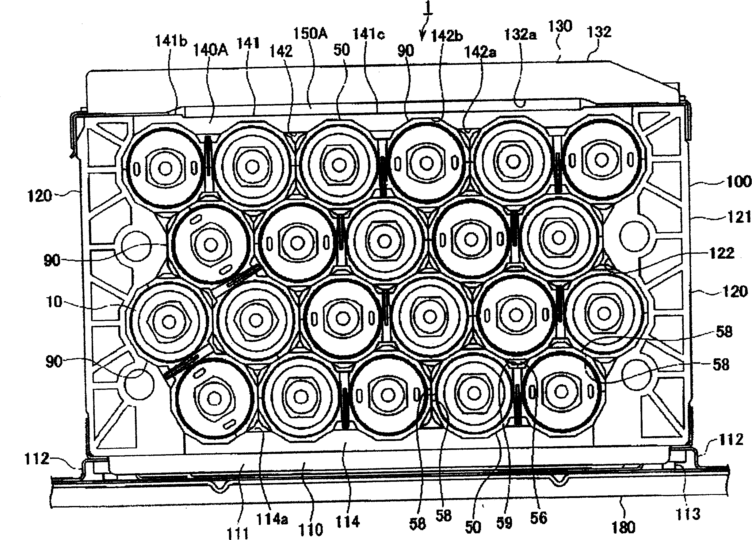
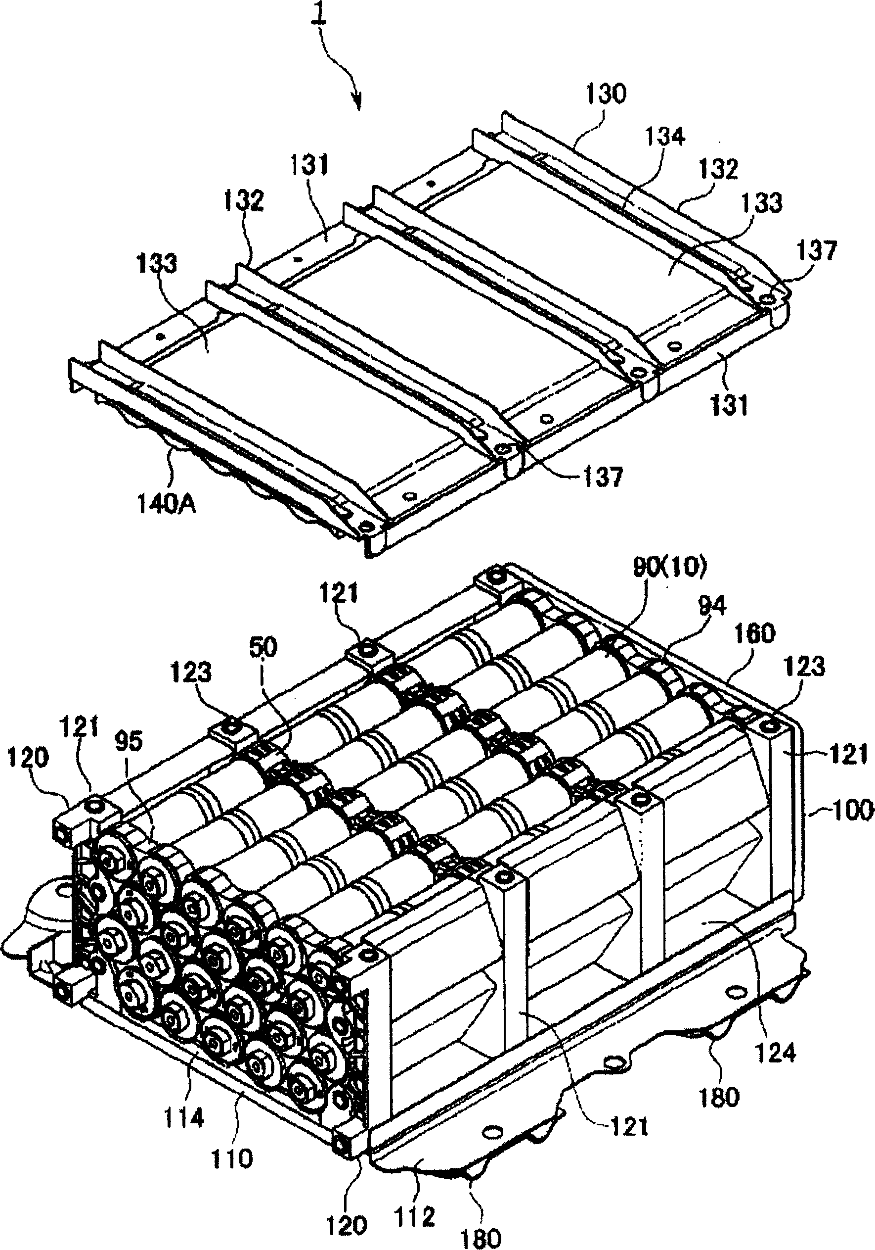
[0023] First, refer to Figure 1 to Figure 7 The accompanying drawings illustrate Embodiment 1 of the battery pack of the present invention. The battery pack 1 of this embodiment is mounted on the back of the seat of an electric vehicle. figure 1 It is a schematic front view of a battery pack 1 in which a plurality (22 in this embodiment) of battery modules 10 are accommodated in a battery case 100 so that their axial directions are parallel to each other. In this battery pack 1 , as shown in FIG. 5 , every two battery modules 10 are bundled with grommets (holding members) 50 in advance to form a battery module unit 90 . Additionally, if figure 1 As shown in , the outer surfaces of the grommets 50 of the battery assembly units 90 adjacent to each other are laminated so that the outer surfaces of the grommets 50 are in contact with each other. According to this configuration, the axial directions of the respective battery modules 10 are arranged parallel to each other, a cer...

Embodiment 2

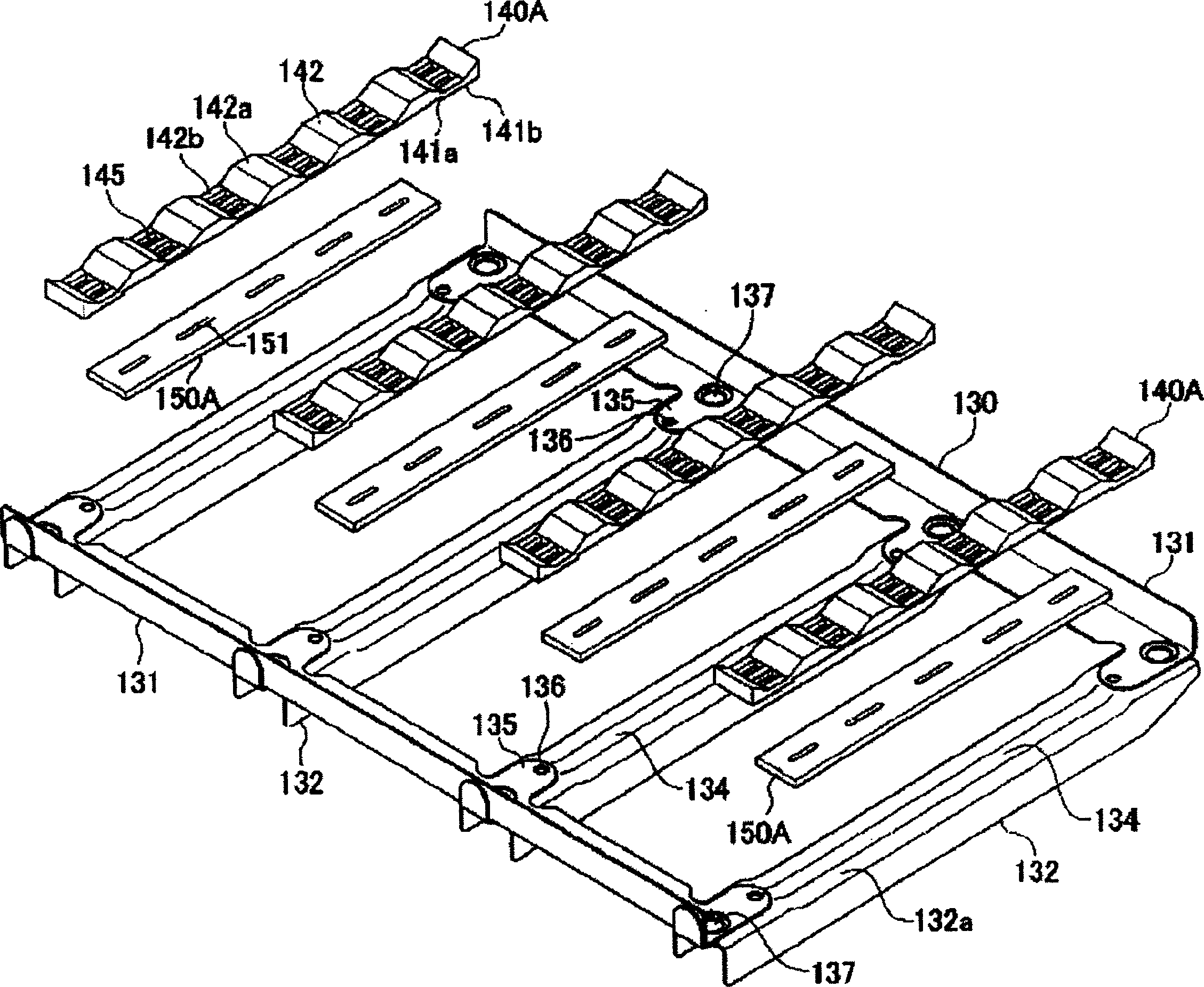
[0042] [Example 2] Below, refer to Figure 8 , Figure 9 The accompanying drawings illustrate Embodiment 2 of the battery pack of the present invention. The battery pack 1 of the second embodiment differs from the structure of the first embodiment only in the upper frame 130 of the battery case 100, the pressing member 140B, and the elastic body 150B. Since the other configurations are the same as those of the first embodiment, the same reference numerals are attached to the same parts, and the description thereof will be omitted. In the battery pack 1 of Embodiment 1 described above, the pressing member 140A and the elastic body 150A are preinstalled on the upper frame 130 , while in the battery pack 1 of Embodiment 2, although the elastic body 150B is preinstalled on the upper frame 130 , but the pressing member 140B is not installed on the upper frame 130 , and is only placed above the guard ring 50 , the process wire cover 94 , and the cover 95 of the uppermost battery m...


PUM


Abstract

A battery pack includes a plurality of cylindrical cell modules, each formed by serially connecting a plurality of unit cells; a cell box in which the cell modules are contained in a manner such that the cell modules are arranged parallel to each other; a plurality of holding members fit to outer peripheries of the cell modules so as to arrange the cell modules in a zigzag manner along axes of the cell modules, in a manner such that the holding members make contact with each other and a gap is secured between every adjacent cell module; and an elastic body inserted between the holding members and a frame of the cell box. Preferably, a pushing member provided between the elastic body and the holding members is provided.

Description

technical field [0001] The present invention relates to a battery pack in which a plurality of battery modules are arranged in parallel in a battery box. Background technique [0002] A battery pack is formed by stacking cylindrical battery modules formed by connecting a plurality of single cells in series in a staggered manner in a battery case (for example, refer to Patent Document 1). In this battery pack, an annular holding member having a polygonal cross-sectional shape perpendicular to the axial direction is attached to the outer periphery of the battery pack at predetermined intervals in the axial direction of the battery pack. In addition, the outer surfaces of the holding members of adjacent battery modules are brought into surface contact with each other, whereby a plurality of battery modules are stacked in a staggered manner. [0003] 【Patent Document 1】 [0004] Japanese Patent Application Publication No. 2003-308816 [0005] However, when the battery modules...

Claims


Application Information

Patent Timeline
Patent Type & Authority Applications(China)
IPC IPC(8): H01M2/10H01M10/50B60K1/04
CPCH01M2/105H01M6/42H01M50/213
Inventor 松冈俊之水谷淳
Owner HONDA MOTOR CO LTD
Features
  • R&D
  • Intellectual Property
  • Life Sciences
  • Materials
  • Tech Scout
  • Unparalleled Data Quality
  • Higher Quality Content
  • 60% Fewer Hallucinations
Learn More