
An apparatus for launching balls for sports practice

A technology of serving device and sports, applied in the direction of valve operation/release device, valve device, weapons without explosives, etc., can solve the problem of not guaranteeing repeated serving, not allowing effective firing, not allowing to adjust the firing speed, etc.

Inactive Publication Date: 2006-12-27
克劳迪奥·贝内蒂 +2
View PDF2 Cites 2 Cited by
  • Summary
  • Abstract
  • Description
  • Claims
  • Application Information

AI Technical Summary

Problems solved by technology

[0015] However, known devices are not suitable for launching footballs in the aforementioned manner
On the one hand, they do not allow the efficient launch of a soccer ball which is of very different weight and diameter compared to a tennis ball
Moreover, such a device does not, on the one hand, guarantee repeated shots and, on the other hand, does not allow adjustment of the firing rate (at least not in an easy and precise way)

Method used


Image

  • An apparatus for launching balls for sports practice
  • An apparatus for launching balls for sports practice
  • An apparatus for launching balls for sports practice

Examples


other Embodiment approach

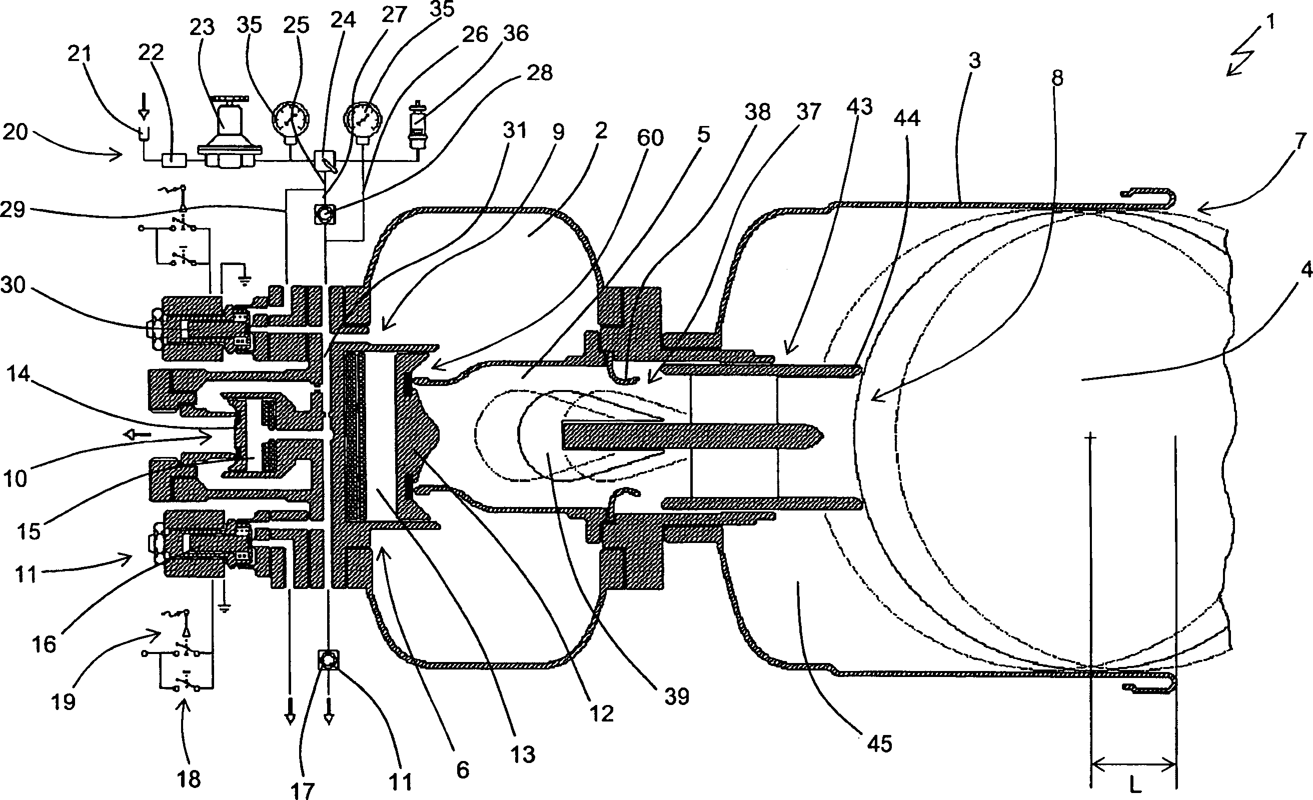
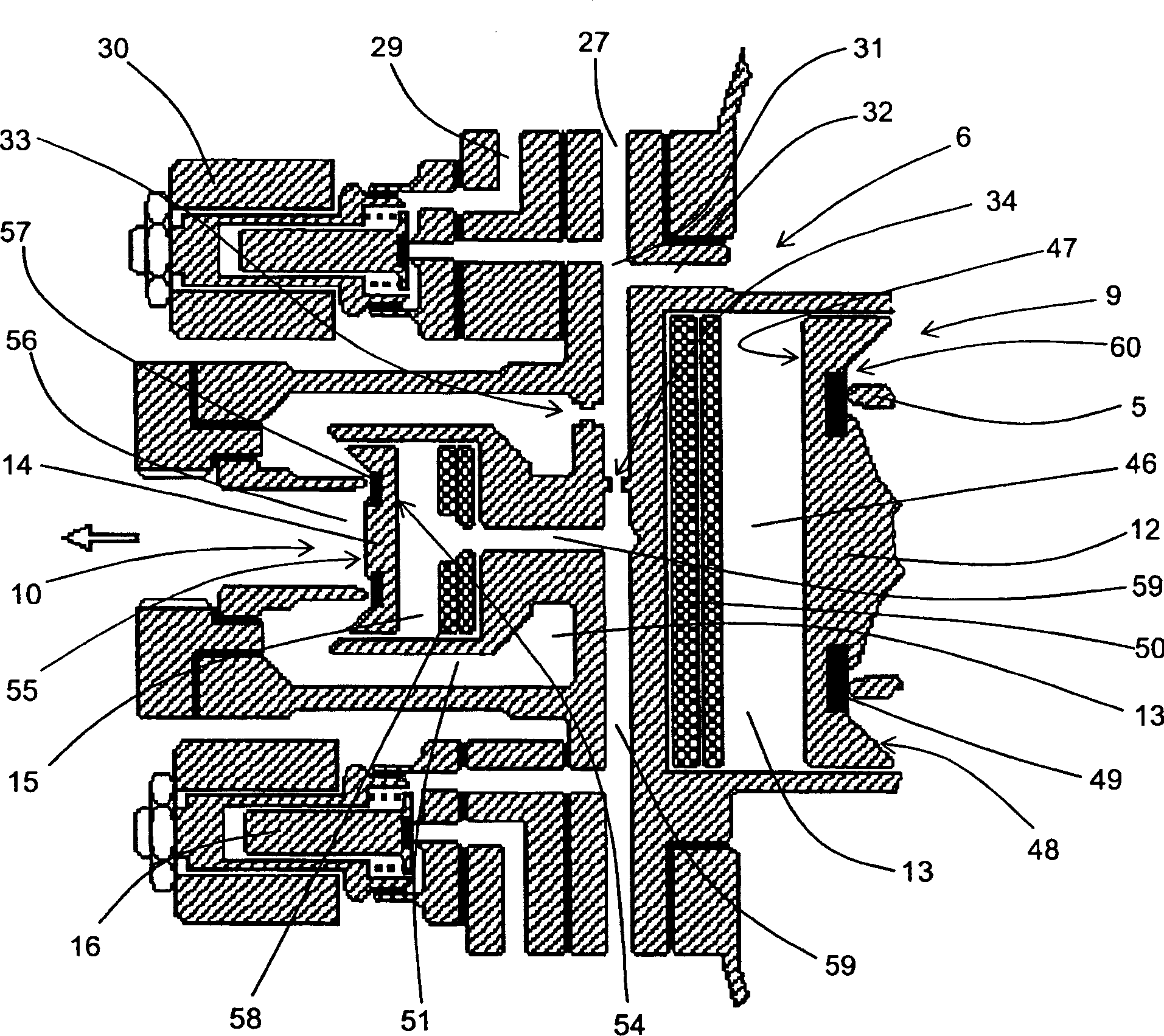
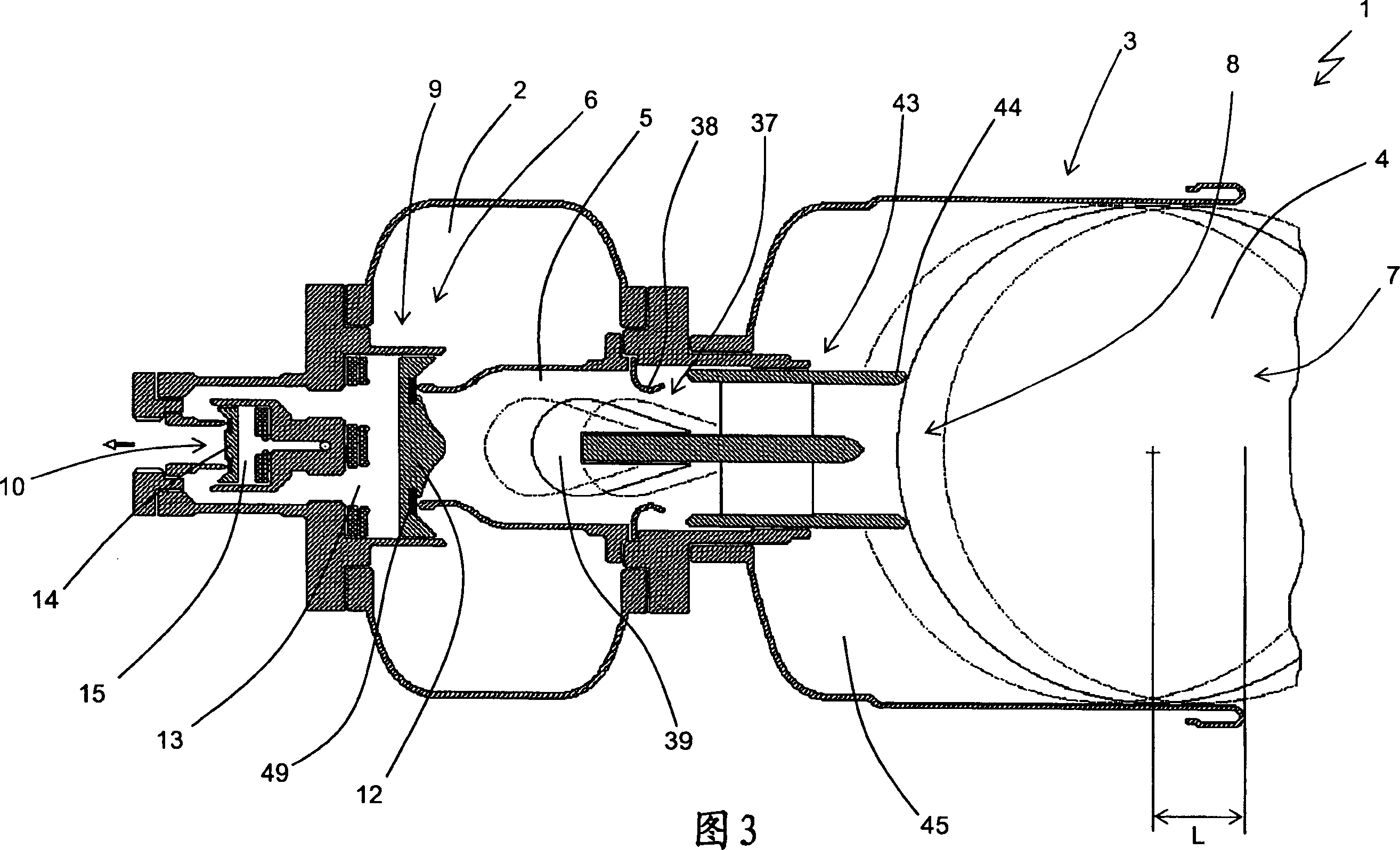
[0036] Other embodiments provide for the use of only the main valve 9 which can be directly actuated by the user, but also for the use of a quick opening main valve 9 which is directly actuated by the actuation valve. In the embodiment shown, the main valve 9 comprises a first movable obturator 12 actuated by means of a first pressurizable chamber 13, said obturator 12 being in the closed position when the first chamber 13 is pressurized, and when the second A chamber 13 moves to the open position when it is depressurized.

[0037] When the control valve 10 is open, it causes the first chamber 13 to decompress in the manner described below.

[0038] With regard to the control valve 10 , like the main valve 9 , it comprises a second movable obturator 14 actuatable by means of a second pressurizable chamber 15 . Likewise, the second obturator 14 is in the closed position when the second chamber 15 is pressurized and moves to the open position when the second chamber 15 is depre...

other Embodiment approach

[0132] Other embodiments are also possible in which, in addition to adjusting the volume of the storage tank 2 , other parameters such as the filling pressure and the effective cylinder length L of the storage tank 2 can also be adjusted.

[0133] As mentioned above, the appropriate dimensions of the first, second and third orifices 32, 33, 34 firstly ensure the closure of the two obturators 12, 14, although the entire circuit is substantially in direct contact with the atmospheric pressure when filling begins, Pressurization of the entire circuit is then ensured.

[0134] Finally, with regard to the noise reduction device 68 , it should be noted that the residual overpressure in the launch tube 3 is relatively high due to the sufficiently high filling pressure of the tank 2 and the limited effective barrel length L . Thus, when the center of the ball passes the open end 7 of the launch tube 3, said open end is arranged to communicate with atmospheric pressure and rapidly vent...


PUM


Abstract

An apparatus for launching balls for sports practice comprising a tank (2) for housing a pressurised gaseous fluid, connected by means of an exhaust duct (5) to a launch tube (3) whose section substantially corresponds to that of a ball (4) to be launched, and which has a seat (8) for positioning the ball (4). A rapid opening device (6) allows to discharge on command the fluid from the tank (2) to the launch tube (3) through the exhaust duct (5), in order to cause the launch of the ball (4). The apparatus (1) further comprises throttling means (37) mounted in the exhaust duct (5) to determine the transfer of the fluid from the tank (2) to the launch tube (3), as well as means (43) for varying the position of the seat (8) for the ball (4) to be launched, which can be operatively associated to each other to vary the position of the seat (8) according to the regulation of the transfer of the fluid from the tank (2) to the launch tube (3) and vice versa, according to a pre-determined relationship.

Description

technical field [0001] The invention relates to a ball serving device for sports practice of the type stated in the preamble of claim 1 . [0002] The device is specifically designed for training soccer players, but it can also be used in any sport or game that uses a ball, such as: tennis, volleyball, American football, rugby, etc. In addition, the device can also be used for simple entertainment games. However, in the following, to simplify the description, only soccer will be explicitly referred to. [0003] It is especially important when training players to provide them with a sequence of serves that, when necessary, repeat in terms of serve speed, value and height arc. [0004] Once the reference ball and the vertical plane within which the trajectory must be contained are set, the altitude arc and launch velocity parameters uniquely identify the trajectory geometry and hourly travel law, allowing immediate evaluation of important parameters such as: range, velocity A...

Claims


Application Information

Patent Timeline
Patent Type & Authority Applications(China)
IPC IPC(8): A63B69/40F41B11/32F16K31/383F16K31/40F16K31/42F41B11/57F41B11/72
CPCA63B69/409F16K31/406F41B11/72F16K31/426F16K31/383F41B11/723F41B11/57F41B11/724F41B11/71
Inventor 阿尔弗雷多·贝内蒂
Owner 克劳迪奥·贝内蒂
Learn More