
Security lock

A technology of anti-theft locks and lock bodies, applied in the field of anti-theft locks, can solve problems such as effective anti-theft, real-time positioning monitoring, remote control of anti-theft locks, etc.

Inactive Publication Date: 2012-05-02
YANTAI TRI CIRCLE SCI & TECH
View PDF0 Cites 0 Cited by
  • Summary
  • Abstract
  • Description
  • Claims
  • Application Information

AI Technical Summary

Problems solved by technology

[0002] At present, there are many styles of anti-theft locks, such as ordinary padlocks, combination locks, card locks, etc., but there is no anti-theft lock that can realize effective anti-theft, real-time positioning monitoring, and remote control.

Method used


Image

  • Security lock
  • Security lock
  • Security lock

Examples


Embodiment approach 1

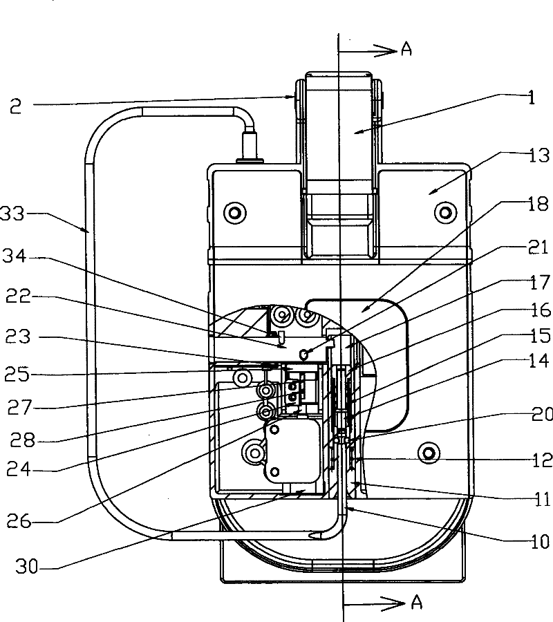
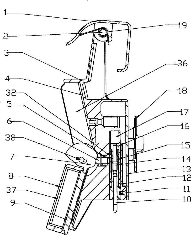
[0032] refer to Figure 1-6 , the anti-theft lock of the present embodiment includes a lock body 3 and a lock cover 13, a lock core 22 is installed on the lock body 3, and a cavity is provided on the lock body 3, which can be fixedly inserted into the locking mechanism, and the lock core 22 cooperates with the locking mechanism to lock , the locking mechanism includes a cable 33 and an insertion shaft 10 connected by the cable 33, the insertion shaft 10 can be inserted into the insertion shaft sleeve 11 correspondingly, the insertion shaft sleeve 11 is fixedly inserted into the lock body 3 through the hole, and the insertion shaft sleeve 11 is covered with an insertion shaft Sleeve spring 12, the insertion shaft 10 is inserted by the insertion shaft sleeve 11 and extends into the insertion shaft outer cover 17 to lock, the insertion shaft 10 is provided with a groove that can snap into the locking steel ball 20 in the locked state, and locks the steel ball in the locked state ...

Embodiment approach 2

[0048] Embodiment 2: The difference between an anti-theft lock in this embodiment and Embodiment 1 is:

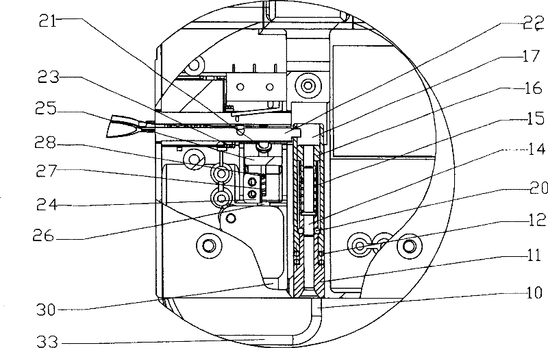
[0049] refer to Figure 7 , a kind of anti-theft lock, its anti-theft lock block 25 is located in the upper stop position when the anti-theft lock is locked, and the implementation mode of blocking the lock cylinder 22 is different:

[0050] The locking mechanism is fixed on the motor shaft 26 by the motor 30 through the motor shaft pin 28. The motor shaft 26 is covered with a motor shaft spring 27 and inserted into the locking block 25, so that the motor 30 is connected to drive the locking block 25 in the upper stop position and the lower stop position. Switch between positions, the upper surface of the lock block 25 is provided with a raised block, and the lock cylinder 22 is provided with a groove that matches the raised block on the upper surface of the lock block 25. When the anti-theft lock is locked, when the lock When the block 25 was positioned at the upper stop ...


PUM


Abstract

The invention relates to an anti-theft lock, and belongs to the lockset technical field. The anti-theft lock comprises a lock body (3), a lock cover (13), and a lock core (22) mounted on the lock body, characterized in that the lock body has a hole chamber to fix an inserted locking device; the lock core (22) is matched with the locking device; the locking device comprises a cable (33) and an insertion shaft (10) connected to the cable; the insertion shaft can be correspondingly inserted into an insertion shaft sleeve (11) which is fixed into the lock body via the hole chamber; the insertion shaft sleeve is sheathed with an insertion shaft sleeve spring (12); the insertion shaft inserts from the insertion shaft sleeve (11) and extends in an insertion shaft sheath (17) to be locked; the insertion shaft sheath (17) is provided with a core shaft (14) matched with the inserted insertion shaft; a core shaft spring (15) sheathed by a core shaft sleeve (16) sleeves out of the core shaft; the insertion shaft outer sleeve has a locating shaft hole (32); and the locating shaft hole can correspondingly insert in a locating shaft (6) sheathed by a locating spring (5) to form lock. The anti-theft lock of the invention effectively realizes the anti-theft purpose, further realizes fixed position surveillance in real time, moreover achieves the purpose of fixed position surveillance in real time and remote control.

Description

1. Technical field [0001] The invention relates to an anti-theft lock, which belongs to the technical field of safety and anti-theft locks. 2. Background technology [0002] At present, there are many styles of anti-theft locks, such as common padlocks, combination locks, card locks, etc., but there are no anti-theft locks that can realize effective anti-theft, real-time location monitoring, and remote control. 3. Contents of the invention [0003] In order to overcome the shortcomings of traditional anti-theft locks, one of the purposes of the present invention is to provide an anti-theft lock that can achieve effective anti-theft purposes, the second purpose is to provide an anti-theft lock that can realize real-time location monitoring, and the third purpose is to provide a An anti-theft lock that can achieve real-time location monitoring and remote control. [0004] The technical solution adopted by the present invention to solve the problems of the technologies descr...

Claims


Application Information

Patent Timeline
Patent Type & Authority Patents(China)
IPC IPC(8): E21B49/00
Inventor 张平马爱民于辉蔡洪义衣鹏飞孙强王磊
Owner YANTAI TRI CIRCLE SCI & TECH
Learn More