Eureka AIR delivers breakthrough ideas for toughest innovation challenges, trusted by R&D personnel around the world.

Lockup control device

A technology of controller and lock release, applied in transmission control, components with teeth, belt/chain/gear, etc., can solve unavoidable shortening of fuel cut-off time, deterioration of fuel consumption rate, shortening of fuel cut-off time And other issues

Active Publication Date: 2007-02-21
NISSAN MOTOR CO LTD
View PDF1 Cites 5 Cited by
  • Summary
  • Abstract
  • Description
  • Claims
  • Application Information

AI Technical Summary

Problems solved by technology

[0007] However, when the vehicle is running or accelerating in a steady state with the automatic transmission locked at a vehicle speed higher than the lock release vehicle speed corresponding to the brake activated state but lower than the lock release vehicle speed corresponding to the brake released state, if The driver changes the position of the leg from the accelerator pedal to the brake pedal (the accelerator is released and the brake is applied), and the state goes through the accelerator released state and the brake released state when the driver changes the leg position, causing the lock to be released
[0008] Therefore, this will lead to a problem of shortened fuel cut-off time and poor fuel consumption rate
[0009] It also brings other problems because even if the locked state is restored by detecting the brake actuated state after the locked state has been released due to the delay occurring between the two states, the shortening of the fuel cut-off time cannot be avoided; Poor vehicle drivability due to fluctuations in engine speed that occur during
[0010] Furthermore, when the vehicle decelerates under the condition that the brake becomes activated at a vehicle speed higher than the lock-release vehicle speed corresponding to the brake-activated state but lower than the lock-release vehicle speed corresponding to the brake-released state, if the driver moves his leg Changing the position of the brake pedal from the brake pedal to the accelerator pedal (the brake is released and the accelerator is applied) can cause similar problems related to fuel consumption and drivability, because the locked state is released when the driver changes the position of the leg

Method used


Image

  • Lockup control device
  • Lockup control device
  • Lockup control device

Examples


Embodiment Construction

[0023] A detailed description of embodiments of the present invention will be given below with reference to the accompanying drawings. The same or similar reference numerals will be used to refer to the same or similar parts in the drawings.

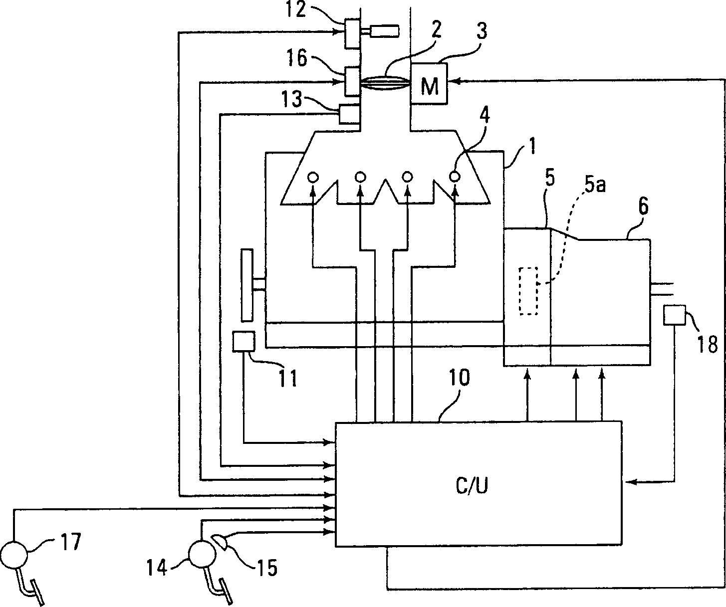
[0024] A preferred embodiment of the present invention is given below with reference to the accompanying drawings. figure 1 is to illustrate the invention as a

[0025] Embodiment system block diagram.

[0026] The electronically controlled throttle valve 2 of the intake system of the engine 1 is connected to a stepping motor (or servo motor) 3 , which is used as a throttle driver, and the motor 3 is driven by a signal from a control unit 10 .

[0027] Each cylinder of the engine 1 is provided with a fuel injection valve 4 driven by a signal from a control unit 10 .

[0028] The control unit 10 is from the crank angle sensor 11 which can detect the engine revolutions per minute Ne, the air flow meter 12 which detects the intake air qu...


PUM


Abstract

Excellent fuel consumption and drivability are achieved by properly controlling the lockup-canceling timing in a vehicle with an automatic transmission equipped with a torque converter having lockup features. In conventional technology, the lockup got cancelled when it was determined that the vehicle speed was lower than lockup-canceling vehicle speed B used when the accelerator was OFF at the same time the brakes were OFF. In the present invention (embodiment), however, delay timer A is activated after the accelerator is released (OFF) to set lockup-canceling vehicle speed A, which is slower than lockup-canceling vehicle speed B and which is used when the brake is activated (ON), so that the lockup will not be cancelled until the vehicle speed reaches vehicle speed A and the lockup period can be ensured for a longer period of time.

Description

technical field [0001] The present invention relates to a lock control device and a control method thereof, and more particularly to a technology related to a control device in an automatic transmission equipped with a torque converter with a lock-up characteristic capable of changing the lock-unlock characteristic according to driving conditions. Background technique [0002] As described in the cited Japanese Laid-Open Patent Publication Nos. JP(A)H6-307535 and JP(A)H11-159608, for a vehicle equipped with an automatic transmission equipped with a torque converter with a lock-up characteristic, by Under various conditions, such as driving at a predetermined speed and other throttle conditions, the torque converter is locked in an attempt to improve fuel consumption. [0003] In addition, a vehicle equipped with a continuously variable transmission as an automatic transmission is also disclosed in cited Japanese Laid-Open Patent Publication No. JP(A) 2001-330127. [0004] H...

Claims


Application Information

Patent Timeline
Patent Type & Authority Applications(China)
IPC IPC(8): F16H61/00
Inventor 影山雄三高桥智彦
Owner NISSAN MOTOR CO LTD
Why Eureka
Eureka Blog
Learn More