Switch device and steering switch device using the same

A technology of switch devices and switch elements, which is applied in the direction of electric switches, transportation and packaging, electrical components, etc. It can solve the problems of thinning the device, misoperation of the actuator, and not easy to add pressing operation, etc., and achieve the suppression height effect of size

Inactive Publication Date: 2007-03-21
ALPS ALPINE CO LTD
View PDF1 Cites 4 Cited by
  • Summary
  • Abstract
  • Description
  • Claims
  • Application Information

AI Technical Summary

Problems solved by technology

However, since the switch device of the above-mentioned prior art is provided with an actuator or a switch element that operates when swinging, the actuator is likely to be pushed downward when the operating member is pressed down to cause a malfunction. Therefore, it is not easy to realize a multi-function such as an additional pressing operation.
Furthermore, if a structure in which an actuator is provided between the operating member and the switch element is adopted like this conventional switch device, the height of the housing increases, making it difficult to achieve the purpose of reducing the thickness of the entire device. question

Method used


Image

  • Switch device and steering switch device using the same
  • Switch device and steering switch device using the same
  • Switch device and steering switch device using the same

Examples


Embodiment Construction

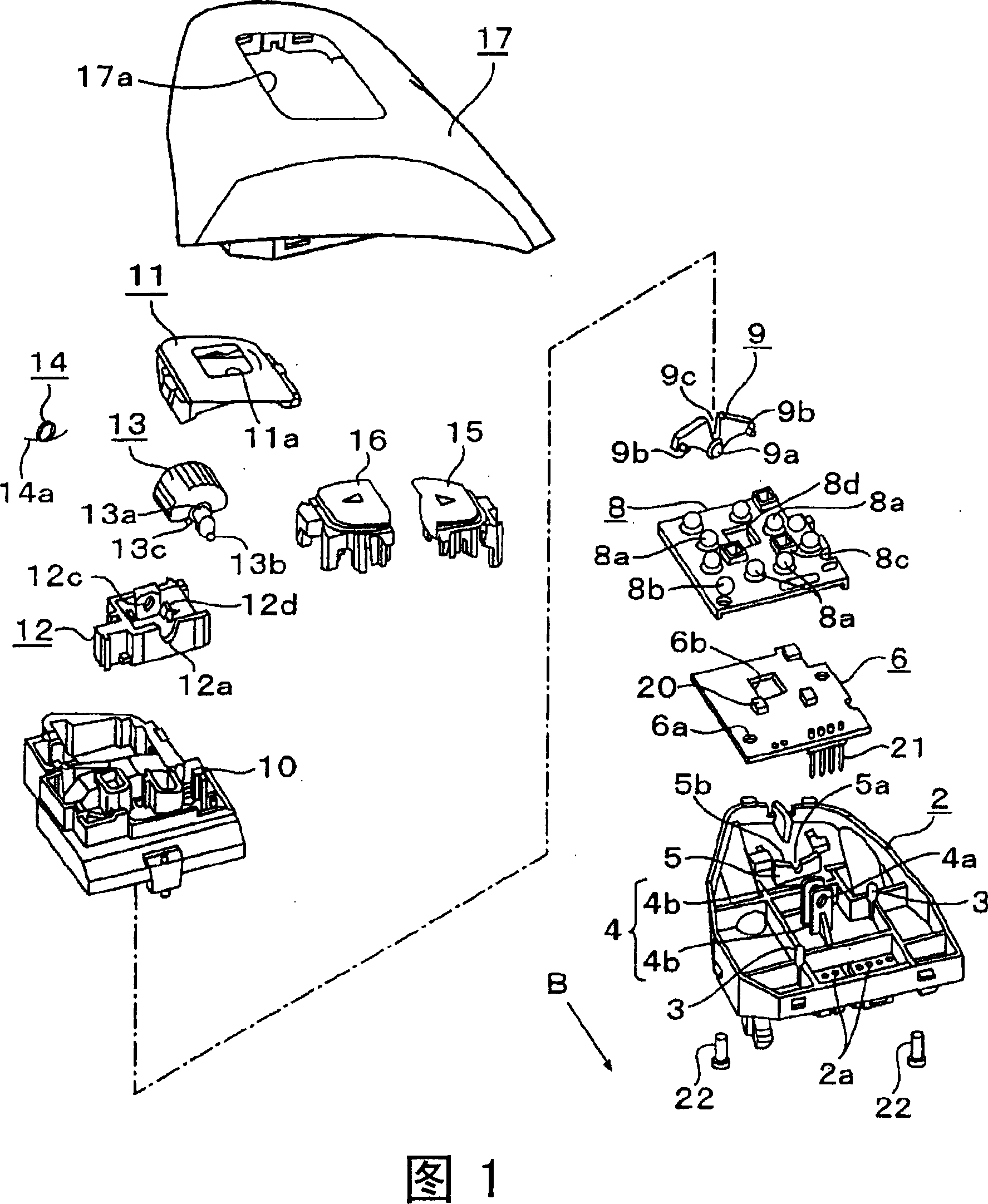
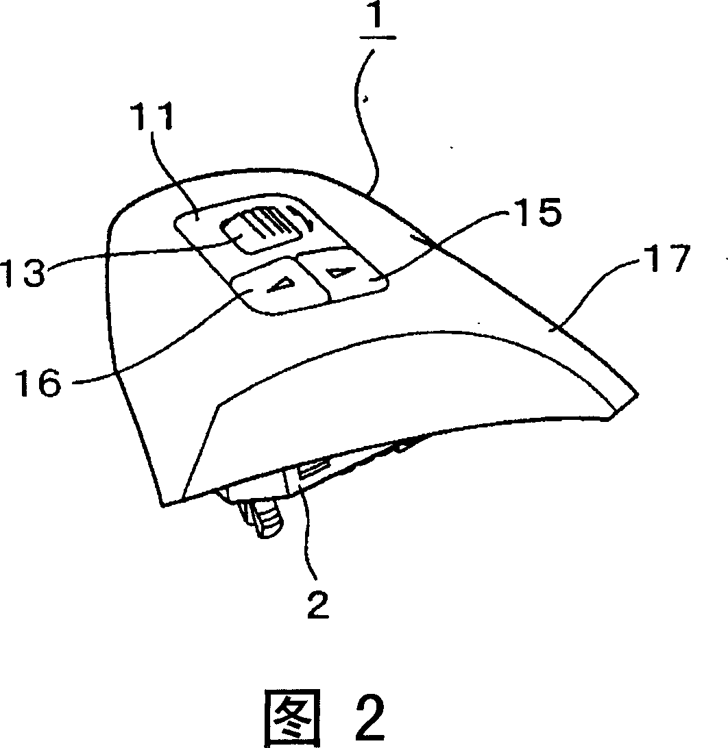
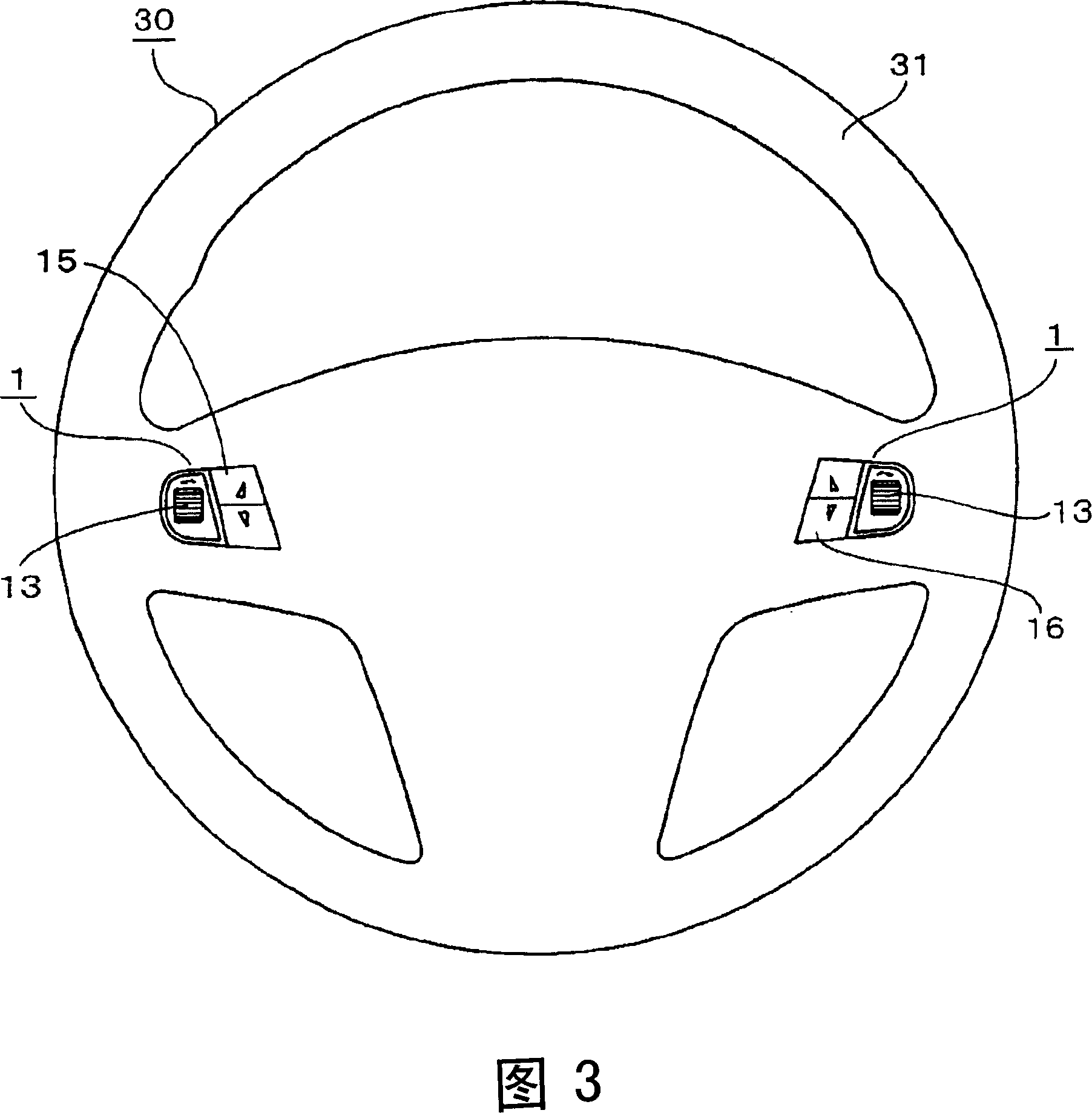
[0022] Embodiments of the invention will be described below with reference to the drawings. 1 is an exploded perspective view of a steering switch device according to an embodiment of the present invention, FIG. 2 is a perspective view showing an assembled product of the switch device, and FIG. 3 is a front view showing a steering wheel on which the switch device is mounted. 4 is an action explanatory diagram when the switch device is rotated, FIG. 5 is a cross-sectional view of the main part of the rubber sheet assembled in the switch device, FIG. 6 is an action explanatory diagram of the return spring assembled in the switch device, and FIG. 7 FIG. 8 is an explanatory diagram of the operation of the switch device when it is pushed down, and FIG. 8 is an explanatory diagram of the malfunction prevention mechanism of the switch device.

[0023] As shown in FIG. 3 , the steering switch device 1 according to the present embodiment is attached in a pair of left and right to the i...


PUM


Abstract

The present invention provides a multi-functional switch device and a steering switch device capable of combined operation of rotation operation and push operation, and which can be easily reduced in thickness. The switch device (1) is provided in the housing (19): a circuit board (6) provided with a fixed contact (7), a bulging portion (8a), a rubber sheet (8) mounted on the circuit board (6) ), the actuator (9) that can be held swingably, the holding member (12) that can be held up and down, and the knob (13) that is supported on the holding member. The actuator (9) is arranged on the side of the knob, and the driving part (13b) attached to the knob extends to the outside of the holding member (12) to engage with the actuator. When the operation knob is rotated, the driving part makes the actuator swing and rotate, and the swing end (9b) presses and drives the bulging part (8a) below; when the operation knob is pressed, the holding member (12) descends integrally to press and drive the lower The bulging part (8a).

Description

technical field [0001] The present invention relates to a switch device capable of selectively switching a plurality of switch elements with the same operating member, and a steering switch device using the switch device. Background technique [0002] As a prior art example of such a switching device, there are known a plurality of switching elements arranged on a circuit board in a housing, an actuator straddling these switching elements, and an actuator that can be mounted on these actuators. The structure of the swinging operation member (see, for example, Patent Document 1). In this prior art switchgear, in order to allow the operator's fingers to operate, a part of the operating member swingably held in the housing is exposed from the window of the housing. When the operating member is operated, due to the actuation Since one end of the actuator is pushed down and the lower switching element is driven by pressing, by selectively pressing both ends of the actuator with ...

Claims


Application Information

Patent Timeline
Patent Type & Authority Applications(China)
IPC IPC(8): H01H25/00B60R16/02
Inventor 白川干夫横山达也崔录铉
Owner ALPS ALPINE CO LTD
Why Eureka
Try Eureka