Switch device and steering switch device using the same

A technology for switch devices and switch elements, which is applied in electrical switches, transportation and packaging, electrical components, etc., can solve the problems of difficulty in achieving thinning of the device, difficulty in additional pressing operations, and increase in the height and size of the housing, and achieves the The effect of height dimension

Inactive Publication Date: 2009-07-08
ALPS ALPINE CO LTD
View PDF5 Cites 0 Cited by
  • Summary
  • Abstract
  • Description
  • Claims
  • Application Information

AI Technical Summary

Problems solved by technology

However, since the switch device of the above-mentioned prior art is provided with an actuator or a switch element that operates when swinging, the actuator is likely to be pushed downward when the operating member is pressed down to cause a malfunction. Therefore, it is not easy to realize a multi-function such as an additional pressing operation.
Furthermore, if a structure in which an actuator is provided between the operating member and the switch element is adopted like this conventional switch device, the height of the housing increases, making it difficult to achieve the purpose of reducing the thickness of the entire device. question

Method used


Image

  • Switch device and steering switch device using the same
  • Switch device and steering switch device using the same
  • Switch device and steering switch device using the same

Examples


Embodiment Construction

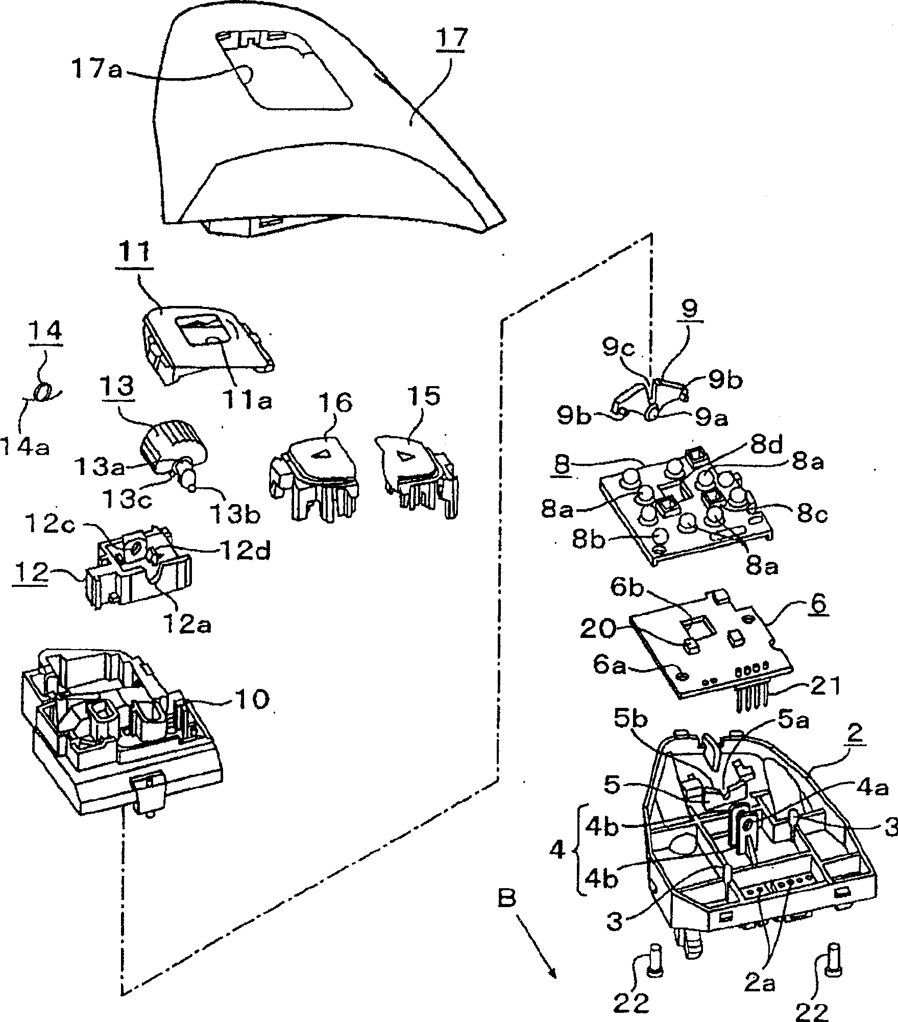
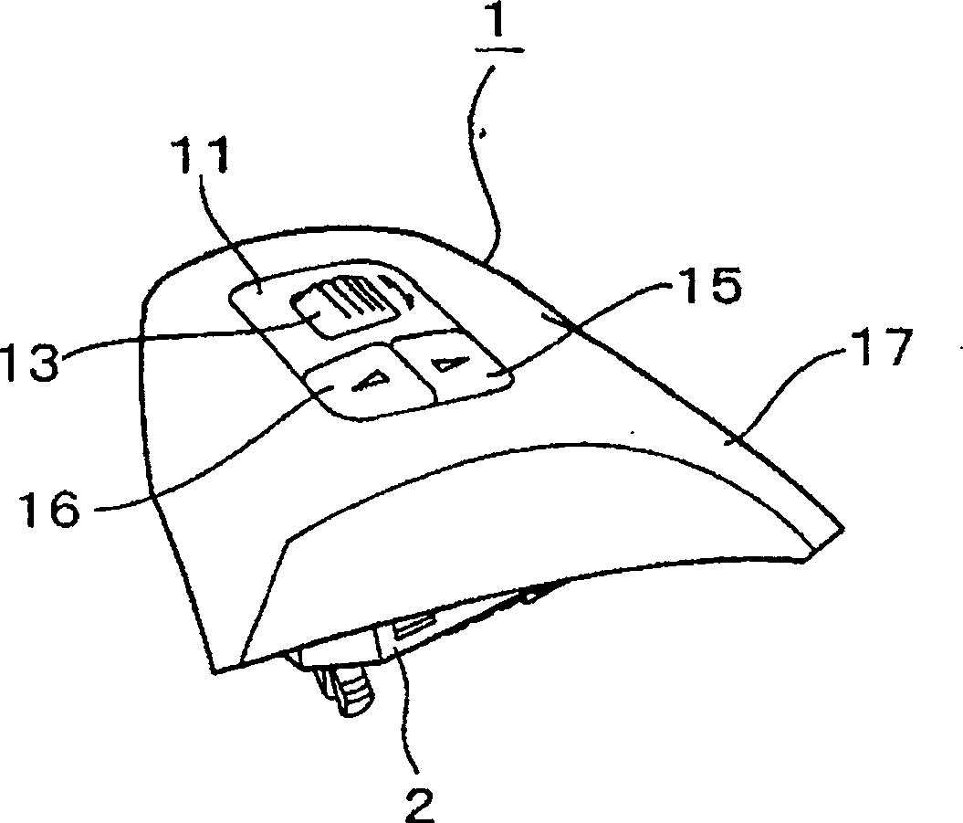
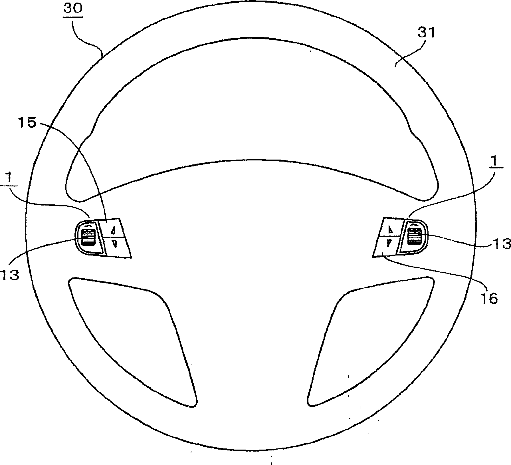
[0022] Embodiments of the invention will be described below with reference to the drawings. figure 1 It is an exploded perspective view of a steering switch device according to an embodiment of the present invention, figure 2 is a perspective view showing the assembled product of the switchgear, image 3 To show the front view of the steering wheel with the switchgear installed, Figure 4 It is an explanatory diagram of the operation when the switch device is rotated and operated, Figure 5 is a sectional view of the main part of the rubber sheet assembled into the switchgear, Figure 6 It is an explanatory diagram of the action of the return spring assembled in the switchgear, Figure 7 It is an explanatory diagram of the operation when the switch device is pressed and operated, Figure 8 It is an explanatory diagram of the malfunction prevention mechanism of this switchgear.

[0023] Such as image 3 As shown, the steering switch device 1 according to the present embo...


PUM


Abstract

The present invention relates to a switch device able to press a plurality of switch element and facility a thin figure and a stearing switch device using the same. A housing 19 for a steering switch device 1 incorporates a circuit board 6 with a fixed contact 7 inside the housing 19. A rubber sheet 8 has a swelling portion 8a, and is mounted on the circuit board 6. An actuator 9 is supported to be able to swing. A rotary knob 13 is supported to be able to rotate. A part of the rotary knob 13 is exposed to the window 11a. This rotary knob 13 is provided with a protruding driver 13b which is engaged with the actuator 9 while sliding. When the rotary knob 13 is rotated, the driver 13b swings and rotates the actuator 9. In turn, a swing end 9b on the actuator 9 performs pushing drive of the swelling portion 8a on the lower side.

Description

technical field [0001] The present invention relates to a switch device capable of selectively switching a plurality of switch elements with the same operating member. Background technique [0002] As a prior art example of such a switching device, there are known a plurality of switching elements arranged on a circuit board in a housing, an actuator straddling these switching elements, and an actuator that can be mounted on these actuators. The structure of the swinging operation member (see, for example, Patent Document 1). In this prior art switchgear, in order to allow the operator's fingers to operate, a part of the operating member swingably held in the housing is exposed from the window of the housing. When the operating member is operated, due to the actuation Since one end of the actuator is pushed down and the lower switching element is driven by pressing, by selectively pressing both ends of the actuator with the operating member, a switch-on signal can be select...

Claims


Application Information

Patent Timeline
Patent Type & Authority Patents(China)
IPC IPC(8): H01H25/00B60R16/02
Inventor 白川干夫横山达也崔录铉
Owner ALPS ALPINE CO LTD
Why Eureka
Try Eureka