Yarn production system

A production equipment and spinning technology, which is used in the production of man-made yarn complete sets of equipment, filament generation, textiles and papermaking, etc. Space saving effect

Pending Publication Date: 2021-04-02
TMT MACHINERY INC
View PDF10 Cites 0 Cited by
  • Summary
  • Abstract
  • Description
  • Claims
  • Application Information

AI Technical Summary

Problems solved by technology

In this case, in order to avoid the increase of the angle of the yarn, it is necessary to lengthen the distance between the first guide and the second guide along the vertical direction, so that the overall height dimension of the yarn production equipment including the spinning device get bigger

Method used


Image

  • Yarn production system
  • Yarn production system
  • Yarn production system

Examples


Embodiment Construction

[0042] (Overall structure of spinning production equipment 1)

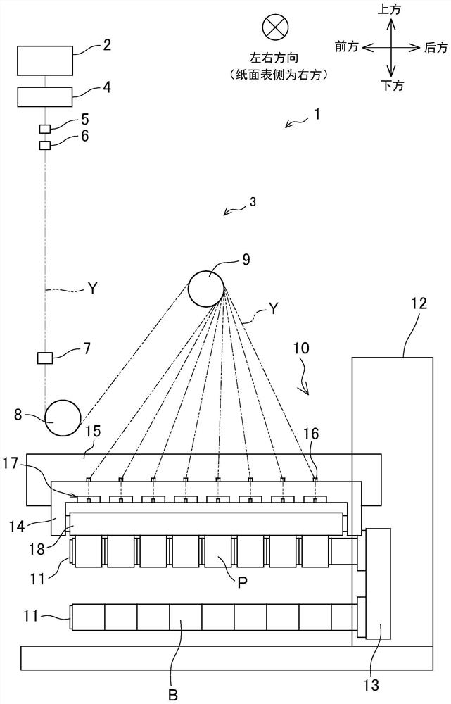
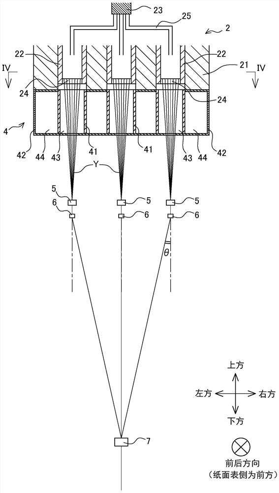
[0043] Hereinafter, preferred embodiments of the present invention will be described with reference to the drawings. figure 1 It is a side view of the spinning production facility 1 according to this embodiment. figure 2 It is a partial sectional view of the spinning device 2 and the cooling device 4 . In addition, the following will figure 1 The front, back, left, right, up, and down directions in are defined as the front, back, left, right, up, and down directions of the spinning production equipment 1 .

[0044] Spinning production equipment 1 such as figure 1 A spinning device 2 and a spinning draw 3 are shown. The spinning device 2 is a device that spins the molten polymer as a yarn Y downward, such as figure 2 As shown in FIG. 1 , a spinning beam 21 and a plurality of spinning packs 22 attached to a housing portion formed under the spinning beam 21 are provided. The spinning drawing device 3 is a devi...


PUM


Abstract

An object of the present invention is to reduce height of a yarn production system including a spinning apparatus having spinning packs, even in a case in which the number of the spinning packs is increased. A yarn production system 1 of the present invention includes spinning packs 22 in each of which molten polymer is stored and each of which spins out a yarn Y downward from a spinneret 24 provided at a lower end portion of each of the spinning packs 22, a spinning beam 21 in which the spinning packs 22 are inserted, first guides 6 which are provided immediately below the spinning packs 22 and which individually guide yarns Y, and a second guide 7 which is provided below the first guides 6 and which causes the yarns Y guided by the first guides 6 to be converged. The spinning packs 22 are arranged along a first arc 51 and a second arc 52 which is inside the first arc 51, in plan view.

Description

technical field [0001] The present invention relates to a spinning production facility equipped with a spinning device having a plurality of spinning packs, and spinning a plurality of yarns downward from a spinneret provided at the lower end of the spinning pack. Background technique [0002] Conventionally, a spinning device for spinning synthetic fiber yarns is known. A general spinning device includes a plurality of spin packs provided with spinnerets at their lower ends. A molten polymer is supplied to a spin pack, and the molten polymer is spun downward from a plurality of nozzles of a spinneret to form a yarn composed of a plurality of filaments. [0003] For example, as shown in Patent Document 1, a spinning device has been developed in which a plurality of spinning packs are arranged in two rows in a zigzag shape when viewed from above. Below the multiple spinning components, a plurality of cooling cylinders that cool the spun yarns by cooling air are arranged in ...

Claims


Application Information

Patent Timeline
Patent Type & Authority Applications(China)
IPC IPC(8): D01D13/00D01D11/04
CPCD01D13/00D01D11/04D01D4/00
Inventor 小岛匠吾
Owner TMT MACHINERY INC
Why Eureka
Try Eureka