Connector of lift main hoist cable

A connecting device and main sling technology, applied in transportation, packaging, elevators, etc., can solve problems such as difficulty in obtaining space saving effects, and achieve space saving effects

Inactive Publication Date: 2005-08-03
HITACHI LTD
View PDF1 Cites 0 Cited by
  • Summary
  • Abstract
  • Description
  • Claims
  • Application Information

AI Technical Summary

Problems solved by technology

[0004] However, in the above-mentioned conventional technology, the sleeve-type connecting rod with a relatively large length dimension is vertically arranged on the upper part of the lifting body, such as the upper part of the elevator car, and is arranged to connect from other parts installed on the upper part of the elevator car. machine protruding
However, according to regulations, when the elevator car is parked on the uppermost floor, a certain distance must be kept between the upper end of the upper machine of the elevator car and the lower end of the top machine of the hoistway. Therefore, in order to save space, it is ideal to be able to Reduction of the height dimension at the top of the hoistway, in addition, due to the length dimension of the telescopic connecting rod, it is difficult to achieve a significant space saving effect

Method used


Image

  • Connector of lift main hoist cable
  • Connector of lift main hoist cable
  • Connector of lift main hoist cable

Examples


Embodiment Construction

[0018] Hereinafter, embodiments of the elevator main rope connecting device of the present invention will be described with reference to the accompanying drawings.

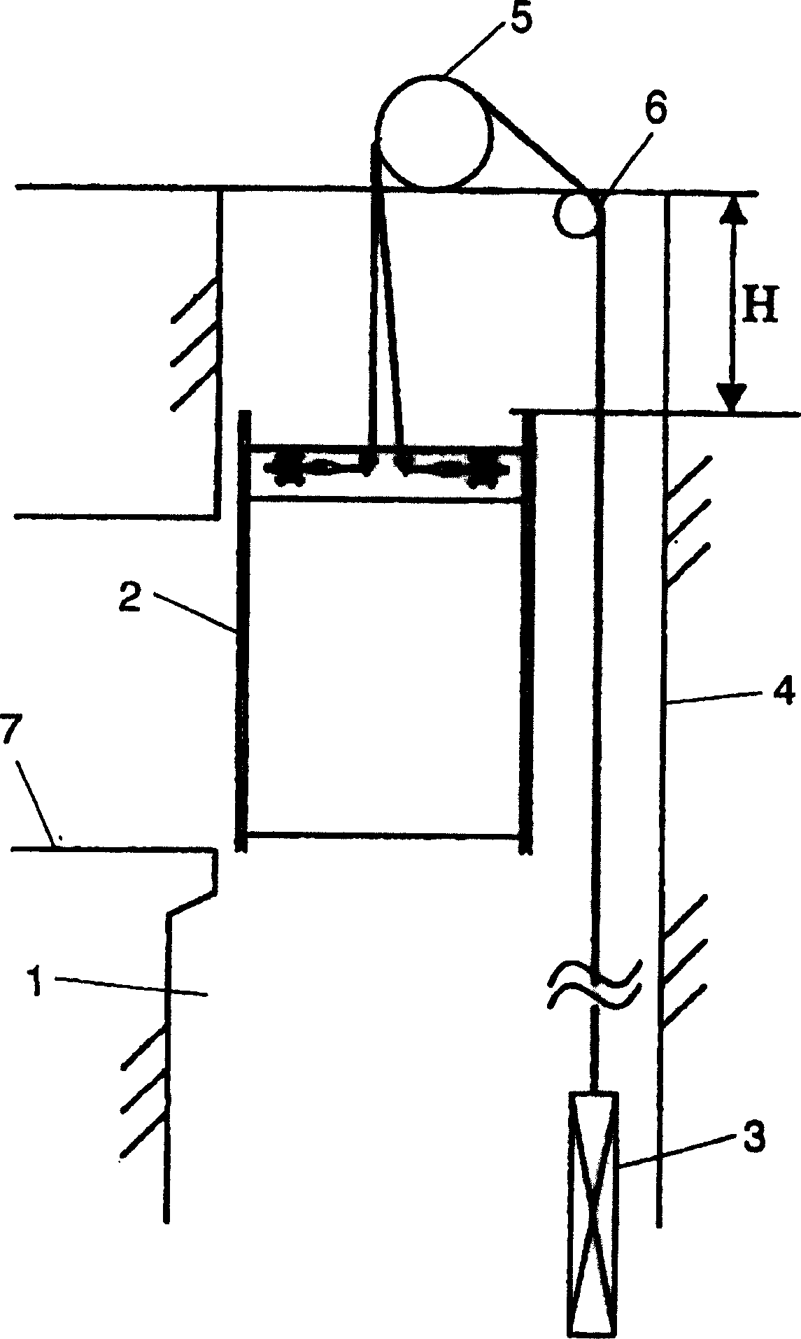
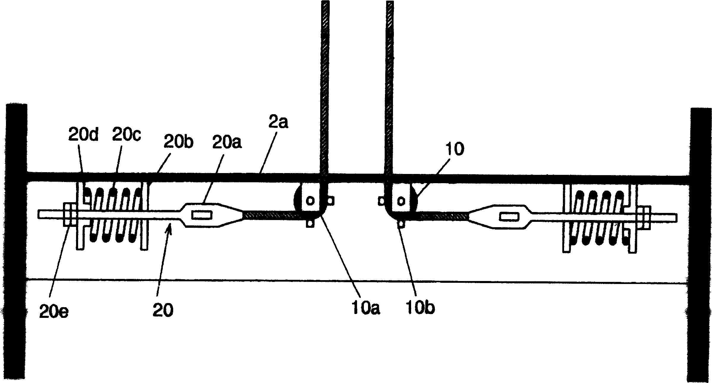
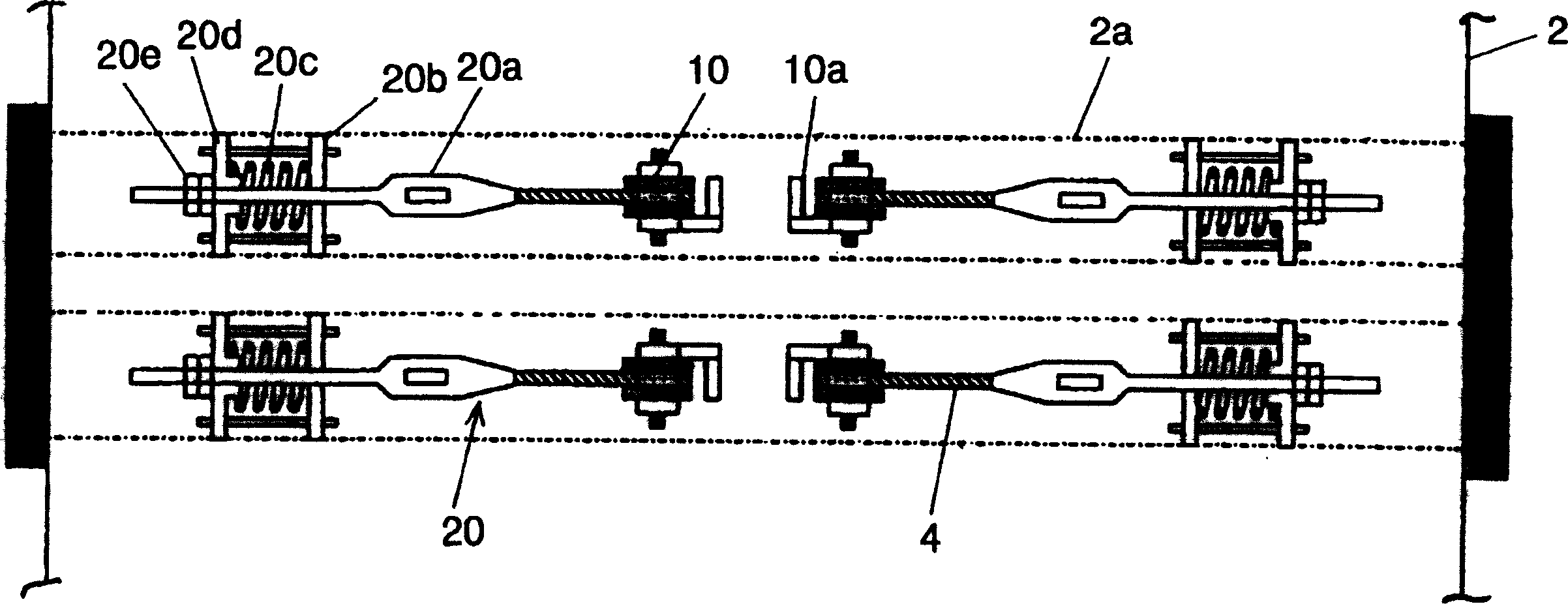
[0019] figure 1 It is a sectional view of the elevator shown in the first embodiment of the present invention. figure 2 It is a side view of the upper part of the elevator car showing the structure of the main part of the present invention. image 3 It is a plan view of the upper part of the elevator car showing the structure of the main part of the present invention.

[0020] like figure 1 As shown, the elevator has a hoisting body that ascends and descends in the hoistway 1, such as an elevator car 2 and a counterweight 3, a main sling 4 connecting the elevator car 2 and the counterweight 3, arranged above the hoistway 1 and The hoist 5 and the diverting pulley 6 wound in the middle position of the main sling 4, according to the regulations, the upper end of the elevator car upper machine when the elevator c...


PUM


Abstract

The invention provided a coupling device for main cables of elevator capable of suppressing the level of the top of a car upper part apparatus. The coupling device for the main cables of the elevator to couple an elevator car 2 rising and falling in a shaft 1 with a plurality of main cables 4 suspending the car 2 through a plurality of thimble rods is equipped with a guide roller 10 installed in the upper part of the car 2 for deflecting the main cables 4 in the horizontal direction, wherein the thimble rods 40 are installed horizontally in the upper part of the car 2.

Description

technical field [0001] The invention relates to a connecting device for an elevator main sling, in particular to a connecting device for an elevator main sling that connects a hoisting body that rises and falls in a hoisting channel with a main sling suspending the hoisting body via a sleeve-type connecting rod . Background technique [0002] As a conventional technique in this field, a plurality of telescopic connecting rods for connecting a lifting body that is raised and lowered in a lifting channel and a plurality of main slings suspending the lifting body are vertically arranged on the upper part of the lifting body ( Refer to Patent Document 1). [0003] [Patent Document 1] Japanese Patent Laid-Open No. 5-32385 (Paragraph No. 0008, figure 1 ) [0004] However, in the above-mentioned conventional technology, the telescopic connecting rod having a larger length dimension is vertically arranged on the upper part of the lift body, such as the upper part of the elevator ...

Claims


Application Information

Patent Timeline
Patent Type & Authority Applications(China)
IPC IPC(8): B66B7/08
Inventor 尾崎淳
Owner HITACHI LTD
Why Eureka
Try Eureka