Device and method for machining long workpieces fixed between two rotating bearings

A technology with long workpieces and rotating shafts, which is applied in the field of high-speed machining, and can solve problems such as not allowing effective suspension of workpieces, and achieve the effects of eliminating shortcomings, high speed, and reducing investment

Inactive Publication Date: 2007-03-28
COMAU SYST FRANCE
View PDF2 Cites 3 Cited by
  • Summary
  • Abstract
  • Description
  • Claims
  • Application Information

AI Technical Summary

Problems solved by technology

The provided workpiece holding device does not allow effective suspension of the workpiece

Method used


Image

  • Device and method for machining long workpieces fixed between two rotating bearings
  • Device and method for machining long workpieces fixed between two rotating bearings

Examples


Embodiment Construction

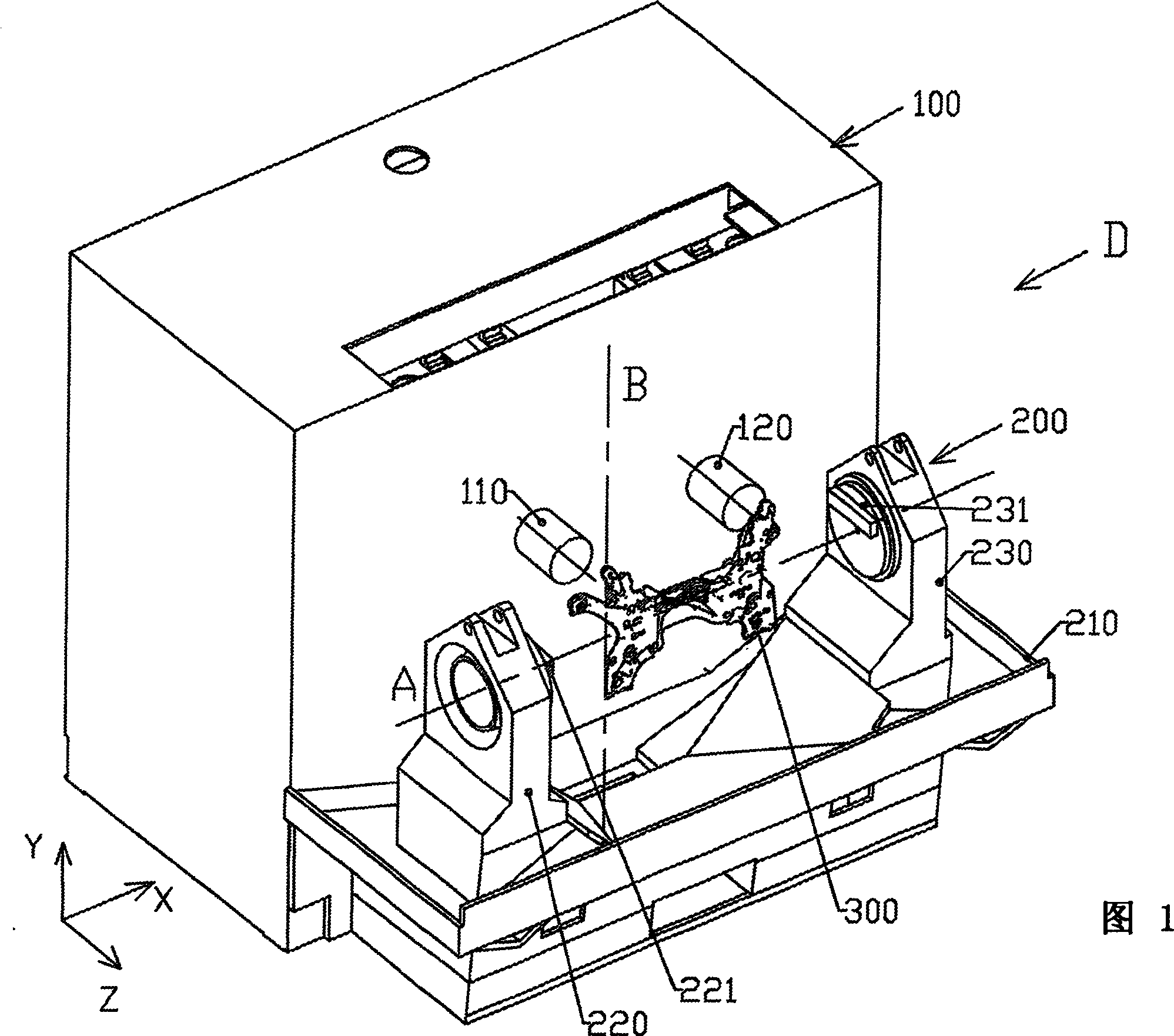
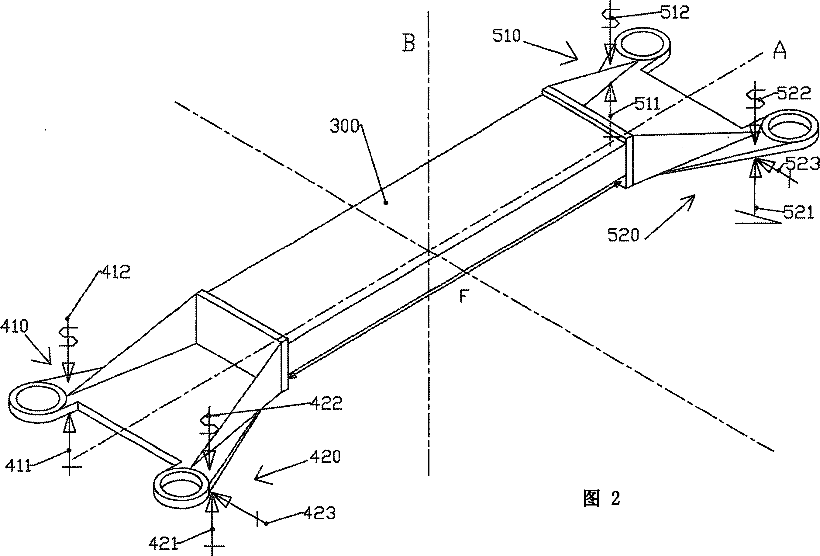
[0048] As shown in FIG. 1 , the machining apparatus generally designated D includes a machine tool 100 and a workpiece holding device 200 in which a workpiece 300 is shown.

[0049] As shown, machine tool 100 is a machining machine tool that has very high speed actuation and maintains an electric spindle for supporting a tool, not shown, along three axes X, Y, Z and independently of each other. The two carriages 110 and 120 are actuated.

[0050] According to a technical option that enables the precision and speed of machining operations to be optimized, the machine tool shown is of the type that it includes guides that are connected with the two carriers along three Corresponding to the linear motion of the two axes, wherein these guide devices include a pair of guide rails, and they realize the above-mentioned independent motions by means of linear linear motors.

[0051] Although, due to the length of the separation distance between the two ends to be machined, the length ...


PUM


Abstract

The invention relates to a machining device (D) such as a device associating a machine-tool (100) with a workpiece holding device (200) having an axis about which the workpiece is rotated transversally (A) in relation to the downward axis (Z), the workpiece to be machined (300) being a long workpiece such as a workpiece comprising surfaces to be machined that are concentrated at the two ends thereof. Said machining device is characterised in that the workpiece holding device (200) consists of a frame (210) supporting two guiding bearings (220 and 230) for rotatably guiding the workpiece according to the transversal rotation axis (A), the structure formed by the frame (210) and the two bearings (220 and 230) being closed by the workpiece to be machined (300) by fixing the ends of the workpiece to the bearings (220 and 230). The invention also relates to a method for machining long workpieces.

Description

technical field [0001] The present invention relates to high speed machining of long workpieces such as those employed in automotive drive trains, and in particular to solutions that improve the quality and duration of such machining. Background technique [0002] Long workpieces used in automotive transmissions, such as frame rear beams or engine mounts, require machining that requires the use of a lathe provided with a tool with five axes of motion. These workpieces have machinable regions mainly at their ends. [0003] So far, designers of manufacturing methods have developed two machining solutions to ensure the manufacture of this type of workpiece. [0004] A first solution consists in carrying out the required machining by means of a conveyor-type machine comprising successive machine tools each dedicated to one machining. Although this solution is fast, it has the disadvantages of being inflexible and requiring a dedicated machine tool. [0005] Another solution c...

Claims


Application Information

Patent Timeline
Patent Type & Authority Applications(China)
IPC IPC(8): B23Q1/52B23Q39/02B23Q1/54
CPCB23Q2039/002B23Q1/5406B23Q39/023Y10T29/5109Y10T82/25Y10T82/2506Y10T82/2552Y10T409/305656Y10T409/305824
Inventor 帕斯奎尔·安吉昂尼
Owner COMAU SYST FRANCE
Why Eureka
Try Eureka