Surface cleaning apparatus

A technology for surface cleaning and equipment, applied in the direction of suction nozzles, etc., can solve problems such as inability to remove

Inactive Publication Date: 2007-04-04
GREY TECHNOLOGY
View PDF2 Cites 16 Cited by
  • Summary
  • Abstract
  • Description
  • Claims
  • Application Information

AI Technical Summary

Problems solved by technology

The brush structure is suitable for collecting and removing larger pieces of debris from the surface, but fine particles (such as dust) cannot be effectively removed from the surface to be cleaned (especially from the crevices and depths of soft furnishings)

Method used


Image

  • Surface cleaning apparatus
  • Surface cleaning apparatus
  • Surface cleaning apparatus

Examples


Embodiment Construction

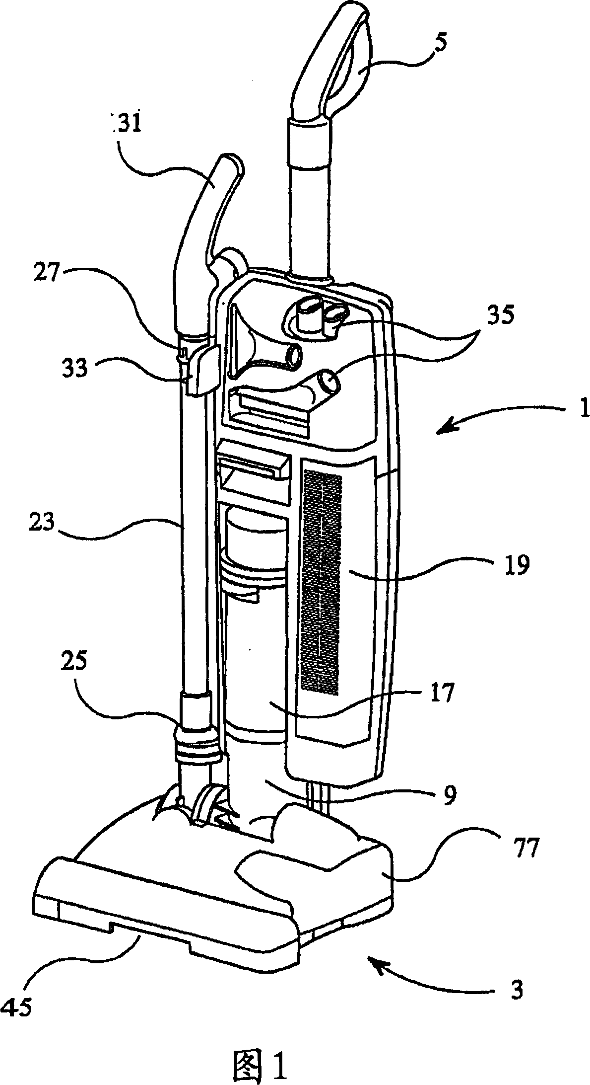
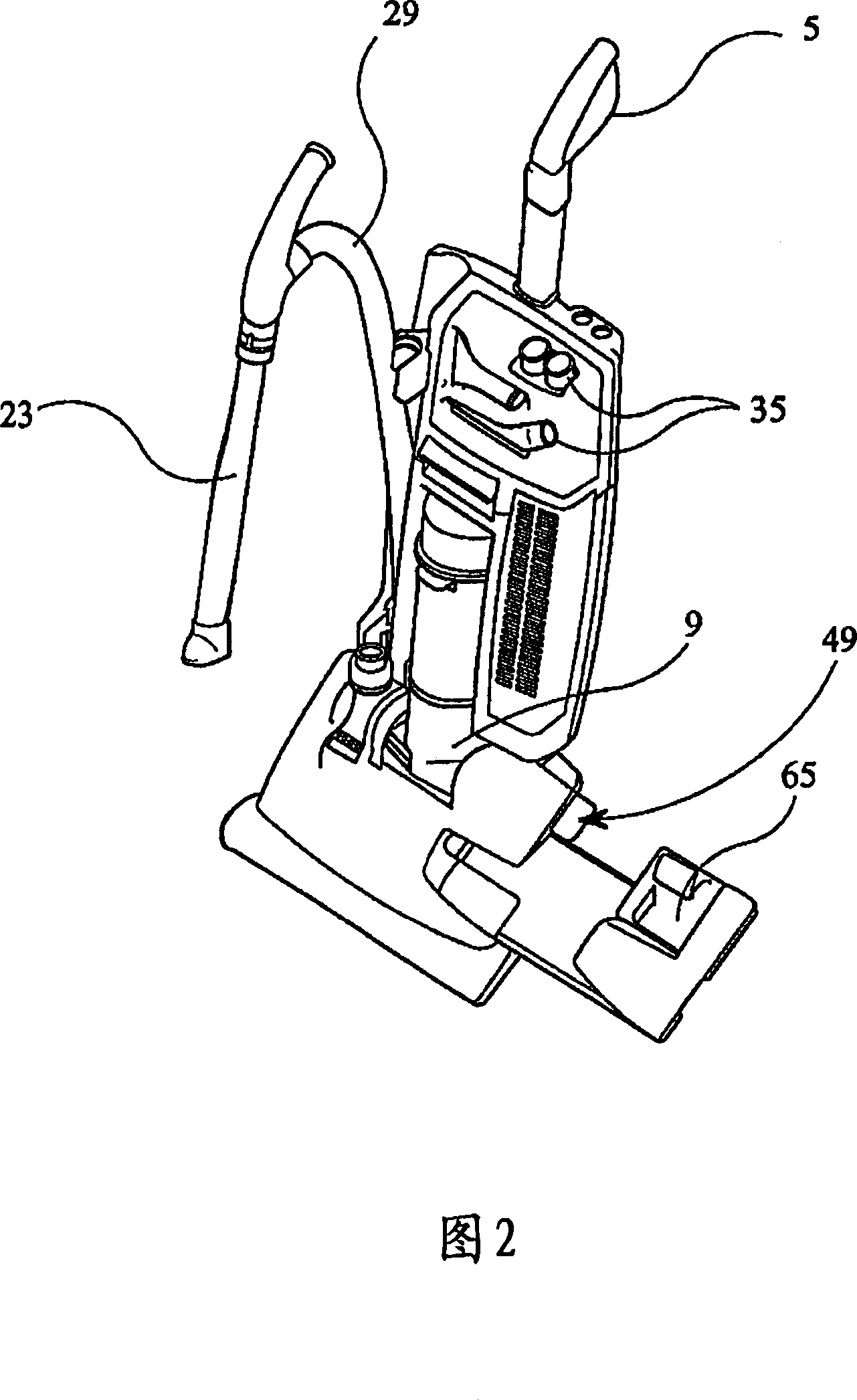
[0068] Referring to FIGS. 1 to 14 , a first embodiment of a surface cleaning appliance in the form of an upright cleaning appliance has a housing comprising a cleaner body 1 pivotally mounted on a debris retrieval body 3 . The cleaner body 1 and the debris retrieval body 3 are suitably molded from plastic.

[0069] The surface cleaning device has a handle 5 provided on the cleaner body 1 so that the surface cleaning device can be manipulated on the surface to be cleaned. The cleaner body 1 is pivotable relative to the debris retrieval body 3 so that the cleaner body 1 can be tilted backwards from the debris retrieval device. The pivoting facilitates movement of the surface cleaning device over the surface to be cleaned.

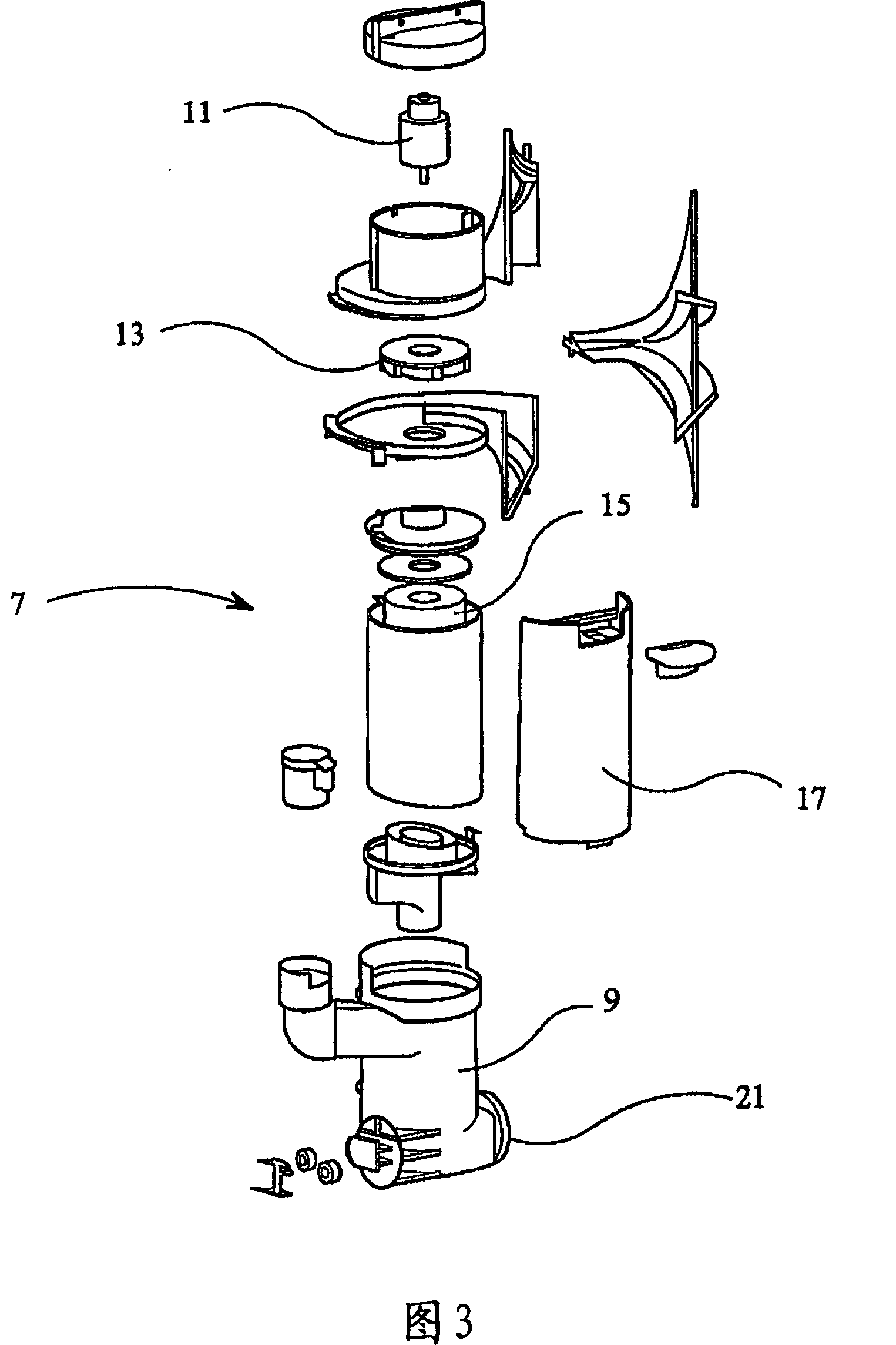
[0070] The cyclonic suction generating assembly 7 is contained in the cleaner body 1 as known to those of ordinary skill in the art. As shown in FIG. 3 , the cyclonic suction generating assembly 7 comprises a cyclonic separator 9 equipped with a motor 11 in...


PUM


Abstract

A surface cleaning apparatus comprising a debris retrieval body (3; 203; 403) and at least one collection means (67; 69; 259; 413; 447) provided within the debris retrieval body for accumulating debris from a surface to be cleaned. A rotatable elongate brush arrangement (39; 223; 427) is also provided within the debris retrieval body to retrieve a first portion of debris from the surface to be cleaned and to direct the first portion of the debris along a first pathway (301; 310; 311) into the at least one collection means. An inlet aperture (61; 255; 475; 485) is provided in the debris retrieval body for the passage along a second pathway (303; 312; 313; 315), independent of the first pathway, of a second portion of debris from the surface to be cleaned. The inlet aperture is formed in a chamber (57; 243; 469; 479) provided within the debris retrieval body and communicating with a means for creating suction, and the inlet aperture has an area less than the cross-sectional area of the chamber such that the speed of air flow through the inlet aperture as a result of the means for creating suction is high relative to the speed of air flow in the chamber.

Description

technical field [0001] The present invention relates to a surface cleaning apparatus using a rotatable brush in communication with suction generating means for retracting debris from the surface. Background technique [0002] In conventional vacuum cleaners, suction generated by a motor is used to withdraw debris, such as dirt dust, from surfaces and the debris is collected in suitable collection means such as filter bags or containers. The amount of debris that can be retrieved from the surface to be cleaned depends on the efficiency of the motor generating the suction. Additionally, it is simply not practical to replace a power line powered motor with a battery powered motor only due to the lower suction that can be generated. [0003] Vacuum cleaners are not suitable for the collection of large debris. The resulting suction can cause the debris collection aperture of the vacuum cleaner to substantially seal against the surface to be cleaned, preventing large debris from...

Claims


Application Information

Patent Timeline
Patent Type & Authority Applications(China)
IPC IPC(8): A47L9/04
Inventor N·G·格雷
Owner GREY TECHNOLOGY
Why Eureka
Try Eureka