Downhole Fluid Treatment Tool

Inactive Publication Date: 2013-07-18
NCS OILFIELD SERVICES CANADA
View PDF6 Cites 24 Cited by
  • Summary
  • Abstract
  • Description
  • Claims
  • Application Information

AI Technical Summary

Benefits of technology

[0008]In accordance with a first aspect of the invention, there is provided a downhole treatment assembly, the assembly comprising: a first housing disposed on a tubing string, the first housing defining a first fluid pathway continuous with the tubing string and including a wall defining a first port for passage of fluid between the first fluid pathway and the wellbore; a second housing disposed on the tubing string above the first housing, the second housing defining a second fluid pa

Problems solved by technology

However, sleeve failure does occur, requiring re-perforation of that wellbore interval.
Such excessive fluid usage limits the economic viability of the operation.
However, when the tubing string is used to deliver treatment fluid, the tubing string may not then be used for other purposes s

Method used


Image

  • Downhole Fluid Treatment Tool
  • Downhole Fluid Treatment Tool
  • Downhole Fluid Treatment Tool

Examples


Embodiment Construction

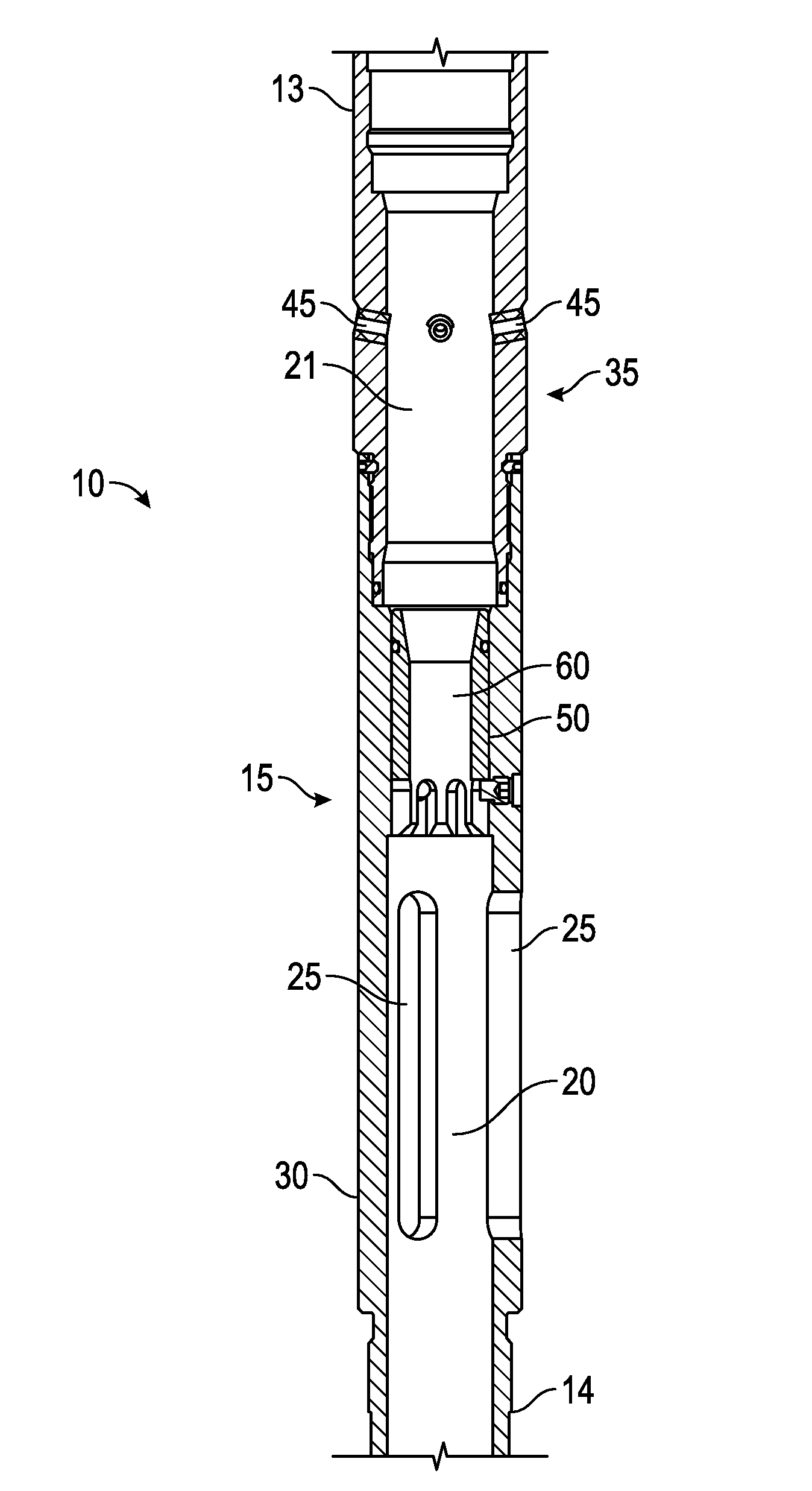
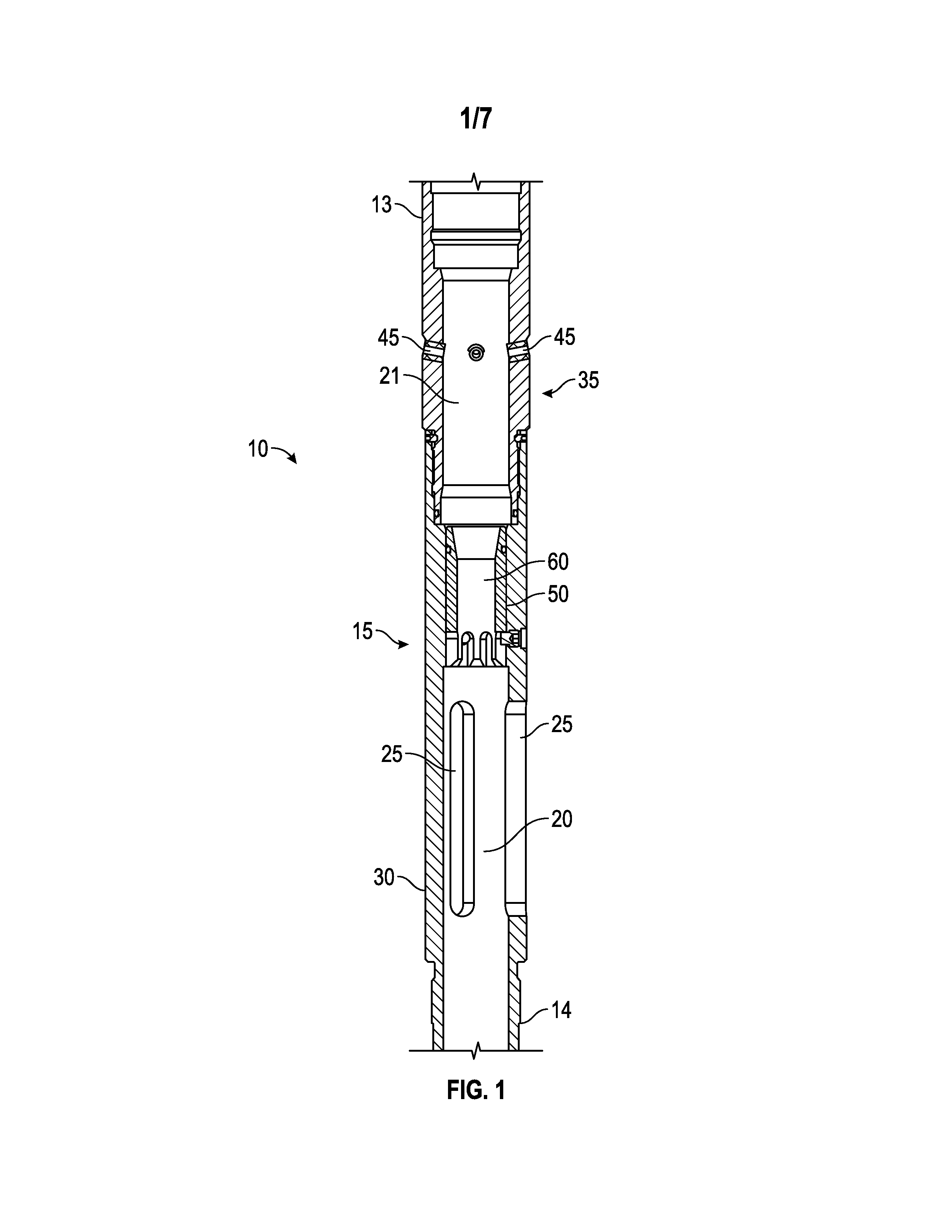
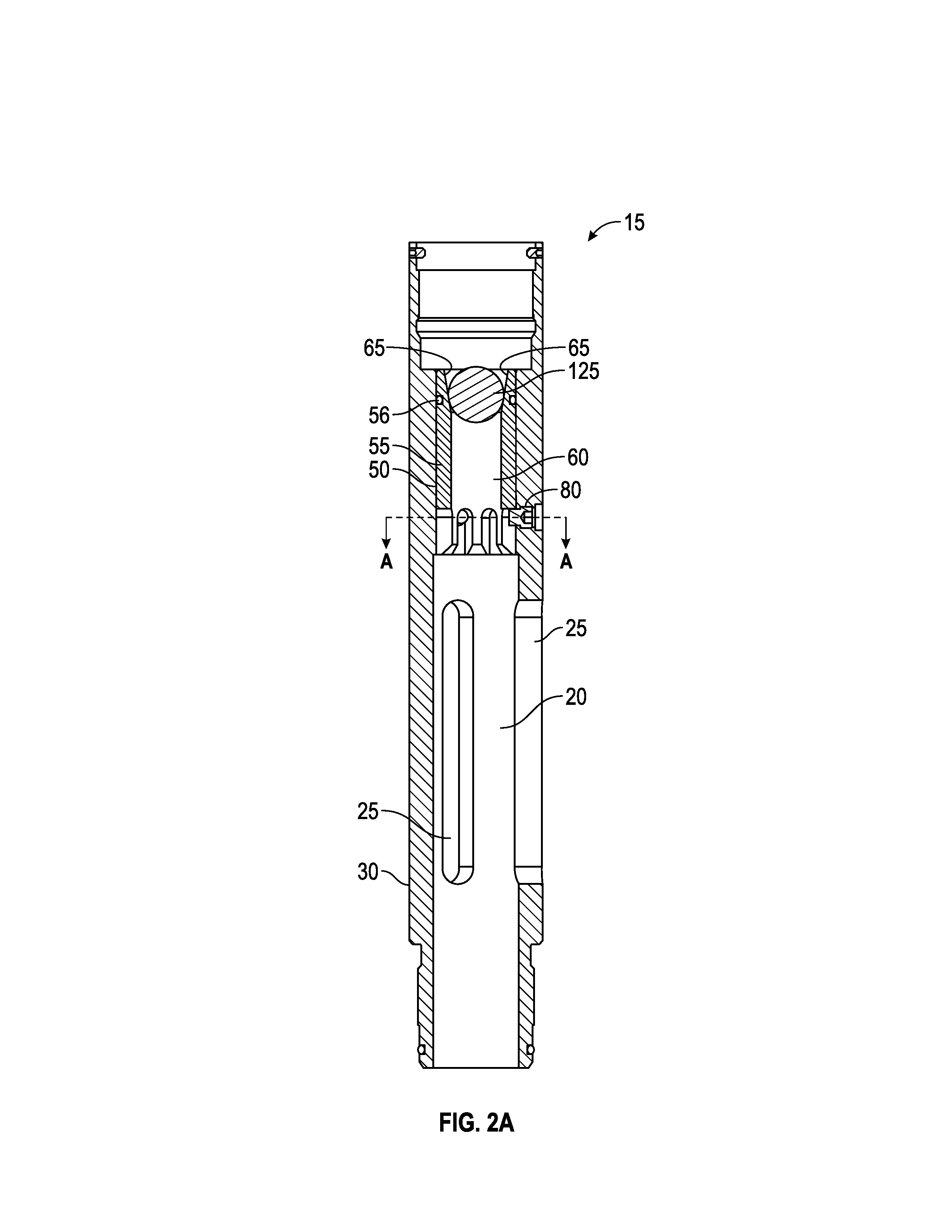
[0030]Generally, the present invention provides a device and method for providing multiple tubing-conveyed fluid pathways through a single tool assembly. Delivery of fluid though a first fluid pathway effects a first fluid treatment within a wellbore interval, while delivery of fluid through a second fluid pathway effects a second fluid treatment within the wellbore. A ball valve allows for diversion of fluid from the first fluid pathway to the second fluid pathway upon delivery of a deformable ball to the ball valve. Hydraulic pressure is applied to force the ball against the seat and thereby build up pressure within the tool assembly and / or tubing string above the sealed ball seat. Once treatment through the second fluid pathway is complete, the deformed ball may be removed, either by reverse circulation from the tool assembly to surface, or may be forced through the seat by application of increased hydraulic pressure so as to deform the ball. Such deformable balls may be engineer...


PUM


Abstract

A treatment device and method for use in delivering fluid treatment to a wellbore is described. The device includes a first treatment housing and a second treatment housing, mounted along a tubing string, each of the first and second housing defining a fluid pathway which is continuous with the tubing string and each of the first and second treatment housing defining a port for fluid communication between the tubing string and the wellbore. Fluid flow through the first housing may be selectively blocked by delivery of a deformable ball to the tubing string to seal against a ball seat disposed between the first and second housing. While the first pathway is blocked, fluid may be selectively delivered to the wellbore through the port on the second treatment housing. The ball may be removed from the ball seat by application of hydraulic pressure in excess of the deformation threshold of the ball, forcing the ball to deform and pass through the seat, re-opening the fluid flow through the first treatment housing and allowing for treatment through port defined in the first housing.

Description

RELATED APPLICATIONS[0001]This U.S. patent application claims priority to U.S. Provisional Application 61 / 580,500 filed on Dec. 27, 2011, the disclosure of which is considered part of the disclosure of this application and is hereby incorporated by reference in its entirety.FIELD OF THE INVENTION[0002]The present invention relates generally to the delivery of treatment fluid to a geological formation intersected by a wellbore. More particularly, the present invention relates to tubing-enabled completions, in which treatment fluid is delivered through tubing to a target interval of the wellbore.BACKGROUND OF THE INVENTION[0003]In completing a cased well, the casing may be perforated in specific locations to provide access to the surrounding formation. Various fluid treatments may be delivered through the perforations, and formations fluids may ultimately be produced through the perforations.[0004]In some wells, the casing may incorporate pre-perforated sleeves, in which the perforati...

Claims


Application Information

Patent Timeline
IPC IPC(8): E21B43/26E21B43/114E21B43/25E21B34/06
CPCE21B34/06E21B43/114E21B34/14E21B43/26E21B43/25E21B34/142
Inventor GETZLAF, DONALDSTROMQUIST, MARTYNIPPER, ROBERT
Owner NCS OILFIELD SERVICES CANADA
Why Eureka
Try Eureka