
Organic el display device

A display device and organic technology, which is applied to lighting devices, static indicators, instruments, etc., can solve the problems of easy deviation of driving current, deviation of brightness of display device, and increase of occupied area, and achieves high resolution and reduces brightness deviation. Effect

Inactive Publication Date: 2007-04-04
ROHM CO LTD
View PDF1 Cites 1 Cited by
  • Summary
  • Abstract
  • Description
  • Claims
  • Application Information

AI Technical Summary

Problems solved by technology

[0008] The driver IC for the organic EL panel has more than 30 output terminals for each of the R, G, and B colors, and the D / A corresponding to these output terminals is generated by a reference current distribution circuit corresponding to the number of output terminals. Therefore, according to the difference in the characteristics of the output-side transistors of the reference current distribution circuit and the relationship between their configurations, the distributed reference currents are prone to deviations.
This results in variations in luminance for each product of the display device or uneven luminance of the display screen
[0009] The driving circuit of the organic EL panel uses a D / A of about 4 to 6 bits to drive the output stage current source, and drives the OEL element through each column pin (each output terminal), which leads to the current conversion of the D / A The accuracy deteriorates, so the drive current corresponding to the column pins is prone to deviation
This variation causes brightness variation for each product of the display device or brightness unevenness of the display screen
[0010] Therefore, there is a problem that the driver IC needs an adjustment circuit for adjusting the reference current on the D / A side in addition to adjusting the reference current, and an output terminal corresponding to this circuit is required, resulting in an increase in occupied area.
[0011] On the other hand, in order to improve the D / A conversion accuracy, if a 6-bit or more D / A is used, the D / A relationship must be set corresponding to each column pin, so the current drive circuit in the driver IC Occupied area increases
Correspondingly, there is a problem that the number of output terminals used is small

Method used


Image

  • Organic el display device
  • Organic el display device
  • Organic el display device

Examples


Embodiment Construction

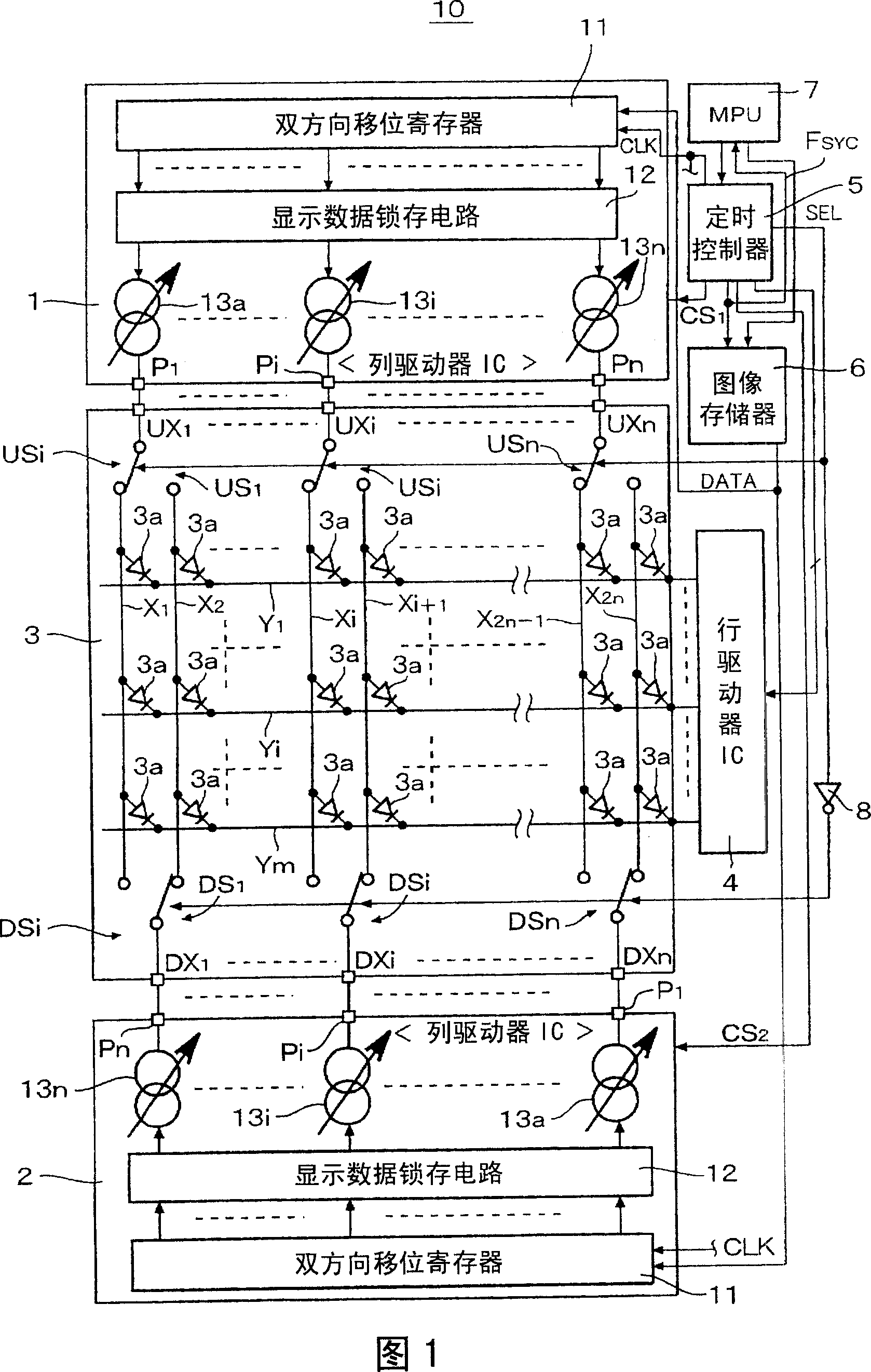
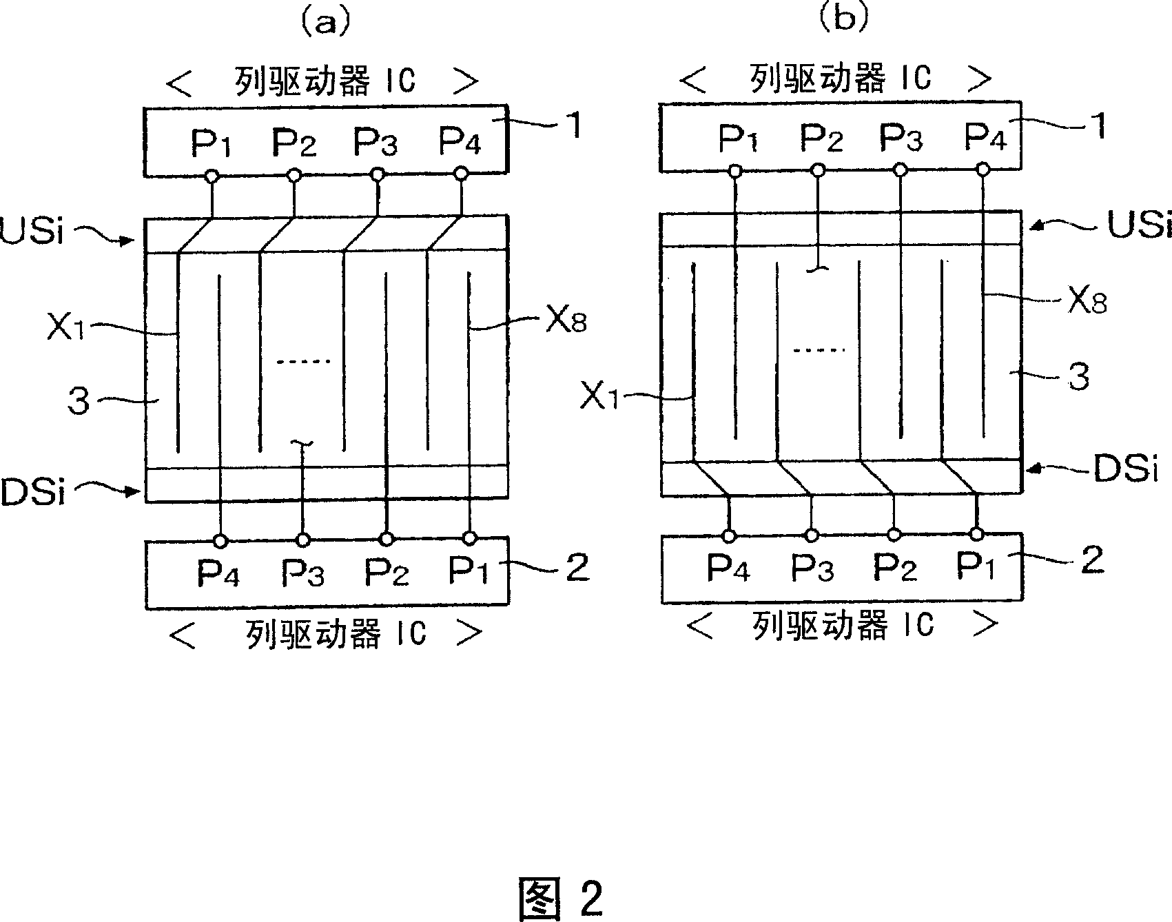
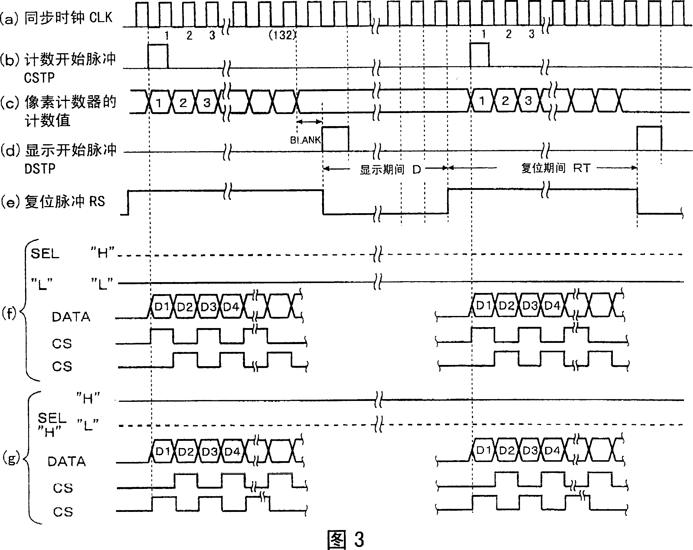
[0030] Fig. 1 is a block diagram showing an embodiment of an organic EL display device to which the present invention is applied, Fig. 2 is an explanatory diagram of the switching state of its column lines, Fig. 3 is an explanatory diagram of timing signals in driver switching, and Fig. 4 is an explanatory diagram of an application of the present invention. FIG. 5 is an explanatory diagram of another embodiment of the organic EL display device of the invention. FIG. 5 is an explanatory diagram of its column line connection switching circuit.

[0031] In FIG. 1, 10 is an organic EL display device, including a column driver IC (hereinafter referred to as a column driver) 1, 2, which sends a driving current to an anode of an OEL element as a current driver; an organic EL panel 3; a row driver IC ( hereinafter referred to as a row driver) 4; a timing controller 5; a screen memory (V-RAM) 6; and an MPU 7.

[0032] The screen memory 6 transmits and stores display data for one frame ...


PUM


Abstract

An organic EL display device (10) is provided with first and second drivers (1, 2), a multitude of switching circuits (US, DS) and a control circuit (5). The first and second drivers are provided with a multitude of output terminals (P). The multitude of switching circuits alternately connect n-number of the output terminal(s) of the first driver (1) (n is an integer of 1 or more) with one and the other of driving lines, which are of the 2n number of organic EL elements and are divided into two, and alternately connect n-number of the output terminal(s) of the second driver (2) with the remaining n-number of the other and the one of the driving lines. The control circuit (5) controls the multitude of switching circuits to switch at the same time by generating a control signal by m frame(s) (m is an integer of 1 or more) or by m horizontal line(s). Thus, brightness variation and brightness nonuniformity can be reduced.

Description

technical field [0001] The present invention relates to an organic EL display device, and specifically relates to an organic EL panel which is current-driven by a plurality of current-driving ICs (current drivers) via column-side terminal pins (column pins), and which can suppress integration into a current-driving IC. The increase in the occupied area of ​​the current drive circuit in the display device reduces the brightness deviation of each product or the brightness unevenness of the display screen, and is suitable for an organic EL display device with a high-resolution organic EL panel. Background technique [0002] In the organic EL display panels of the organic EL display devices mounted in mobile phones, PHS, DVD players, PDAs (portable terminal devices), etc., a method for driving the anode side of the organic EL element with the column line (column line) has been proposed. The number of terminal pins on the column side connected to the drive line is 396 (132×3), an...

Claims


Application Information

Patent Timeline
Patent Type & Authority Applications(China)
IPC IPC(8): G09G3/30G09G3/20H05B33/06H05B33/14H05B44/00
CPCG09G3/3283G09G2320/0233G09G3/3216H05B33/0896H05B45/60Y02B20/30G09G3/30H05B33/06G09G3/32G09G3/20
Inventor 前出淳阿部真一藤泽雅宪
Owner ROHM CO LTD
Learn More