
Low power laser irradiator for treating alopecia

A laser irradiation, low-power technology, applied in the direction of treatment, phototherapy, radiation therapy, etc., can solve the problems such as no treatment method

Inactive Publication Date: 2007-04-25
OSTERN
View PDF1 Cites 10 Cited by
  • Summary
  • Abstract
  • Description
  • Claims
  • Application Information

AI Technical Summary

Problems solved by technology

In fact, there is still no excellent treatment to meet the needs of hair loss patients

Method used


Image

  • Low power laser irradiator for treating alopecia
  • Low power laser irradiator for treating alopecia
  • Low power laser irradiator for treating alopecia

Examples


Embodiment Construction

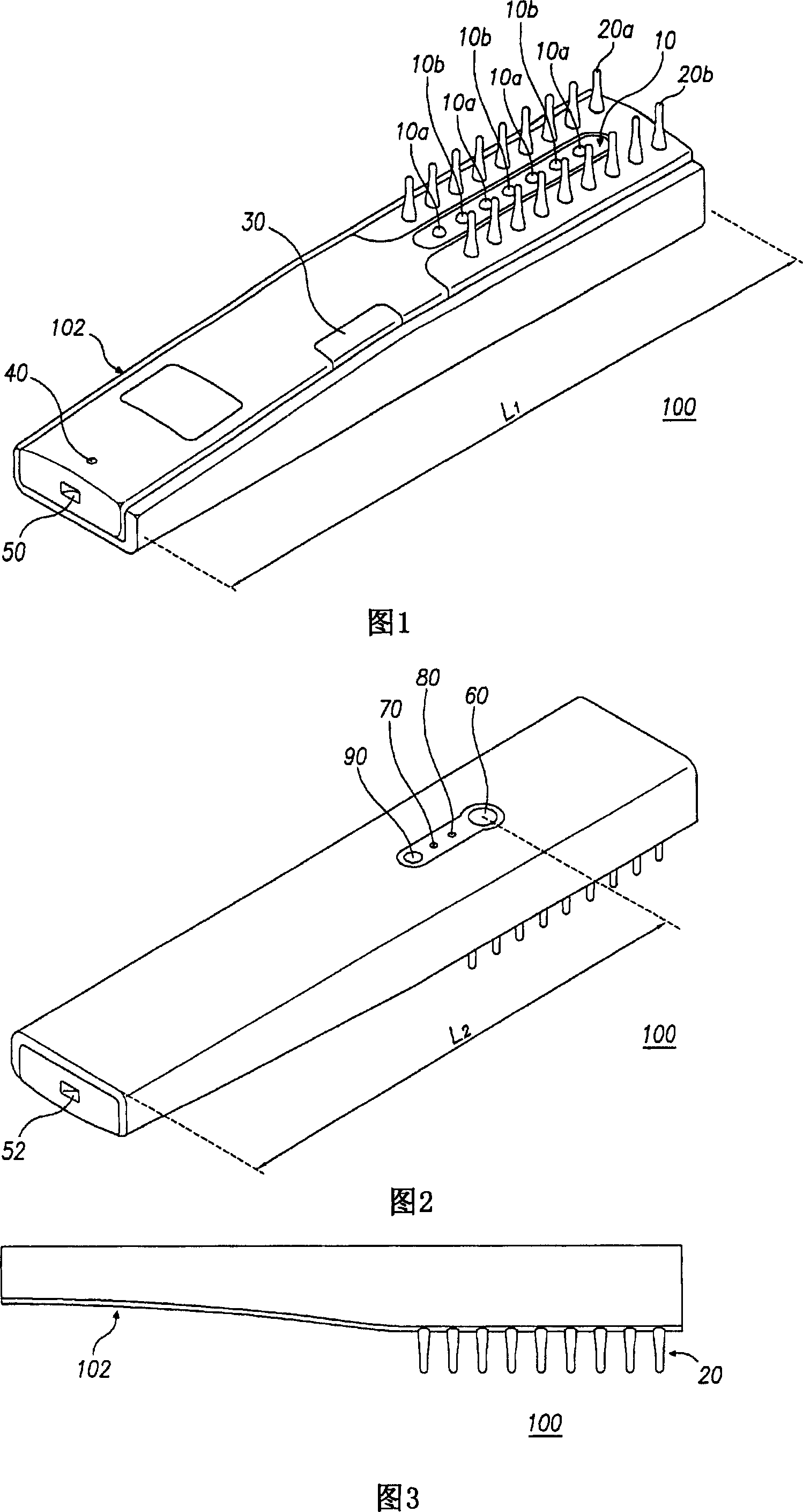
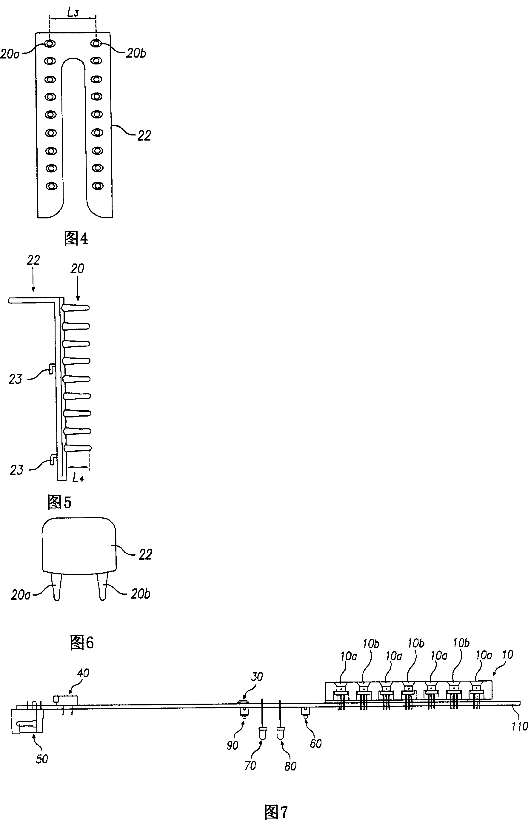
[0026] 1 to 3, the laser irradiator 100 of the present invention includes a laser output unit 10, a first comb 20a, a second comb 20b, a laser switch button 30, a loudspeaker 40, a power inlet 50, a power switch button 60, and a sound indicator light 70. Power indicator light 80 and sound switch button 90. When the user uses the handle 102 to comb his hair, the laser irradiator 100 sends out laser light to the scalp.

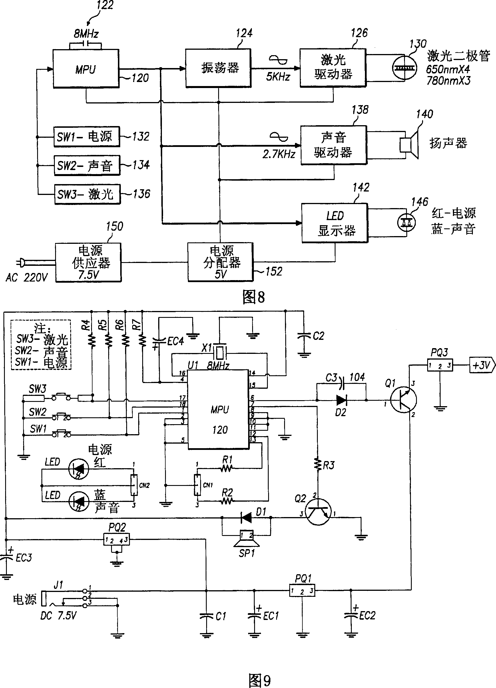
[0027] The laser output unit 10 is provided with four red laser diodes 10a with a wavelength of 630nm to 680nm and three near-infrared laser diodes 10b with a wavelength of 750nm to 1000nm, which are alternately arranged in a row. Preferably, the length of the laser output unit 10 should be able to provide sufficient laser irradiation range, so that effects such as increasing scalp blood flow can be obtained when the laser irradiator 100 is used for general combing. For example, the length of the laser output unit 10 is 60 mm. Preferably, the laser output unit...


PUM


Abstract

A low-power laser irradiator of the present invention activates hair follicle cell and increases blood flow of scalp tissue, thus enhancing effects of hair loss prevention and hair regrowth. The laser irradiator includes a laser output unit in which red laser diodes with 630nm~680nm wavelength and near-infrared laser diodes with 750nm~1000nm wavelength are arranged alternatively. The comb-shaped laser irradiator is convenient to use through typical combing action and effectively used for alopecia treatment.

Description

technical field [0001] The present invention generally relates to a low-power laser irradiator, especially a low-power laser irradiator that can be used to treat hair loss by arranging alternately laser diodes with different output wavelengths. Background technique [0002] Human hair grows on the scalp during a growth cycle that includes three phases: anagen, catagen, and telogen before falling out. Generally speaking, human beings have about 100,000 hairs at birth, and about 80 hairs are shed from the scalp every day. Alopecia means more hair is falling out than growing. Hair loss may be caused by testosterone, which is converted into dihydrotestosterone (dihydrotestosterone, DHT) under the action of 5α reductase, and then binds to the androgen receptor. DHT weakens the function of the dermal papilla and hair follicles, which can lead to hair loss. Hair loss can be caused by many reasons, such as genetic factors, hormonal imbalance, psychological stress, environmental p...

Claims


Application Information

Patent Timeline
Patent Type & Authority Applications(China)
IPC IPC(8): A61B18/20A61N5/06A61N5/067
CPCA61N2005/0658A61N5/0616A61N2005/067A61N2005/0652A61N2005/0644A61N5/0617A61N2005/0659A61N5/067
Inventor 片雄范
Owner OSTERN
Learn More