Plating tank

A technology of electroplating tank and current, applied in the direction of plating tank, electrical components, electrolysis process, etc., can solve the problems of unable to prevent the plate-shaped workpiece W from shaking, unable to uniform quality, easy to break, etc.

Active Publication Date: 2007-05-16
C UYEMURA & CO LTD
View PDF5 Cites 27 Cited by
  • Summary
  • Abstract
  • Description
  • Claims
  • Application Information

AI Technical Summary

Problems solved by technology

[0018] However, in the prior art as described above, although the current concentration at the front and rear ends of the plate-shaped workpiece W can be prevented, it is sometimes impossible to achieve uniform quality by the jet flow of the plating solution, and it is also impossible to prevent the current from flowing to the plate-shaped workpiece W. The upper and lower ends are concentrated to achieve a uniform plating film thickness
[0019] For example, in Patent Documents 2 and 3, uniform plating quality is achieved by rectifying the jet flow of the electroplating solution through a louver. The louver sometimes acts as a current shield beyond the necessary limit, and sometimes reduces the plating efficiency. low, or degrade the plating quality
In addition, although there is a shielding plate at the lower end of the plate-shaped workpiece W, the current may be detoured (まわり込み), etc., and the current shielding effect cannot be obtained sufficiently, and the current may concentrate on the upper end of the plate-shaped workpiece W. and the lower end, resulting in deviations in the thickness of the plating film
[0020] In addition, in order to prevent the plate-shaped workpiece W from shaking, a Teflon linear body is used as a guide. However, the Teflon linear body contacts the plate-shaped workpiece W and is easily broken. As a result, the plate-shaped workpiece W may not be prevented. Shaking of workpiece W
In addition, it is also possible to provide a metal core material in the Teflon linear body so that it will not be broken, but when the Teflon resin peels off and the metal core material is exposed, the plate-shaped workpiece W may hit the metal core material. The exposed metal core material causes scratches, or sometimes the plating layer attached to the metal core material is mixed into the treatment solution, deteriorating the plating quality
In particular, when the plate-shaped workpiece W is a thin-plate substrate with a thickness of 0.1 mm or less, it is easy to shake or skew due to the above-mentioned plating jet flow, and the plate-shaped workpiece W moves forward while sliding in contact with the plate-shaped workpiece W, so the plate-shaped workpiece is very difficult. prone to chafing

Method used


Image

  • Plating tank
  • Plating tank
  • Plating tank

Examples


Embodiment Construction

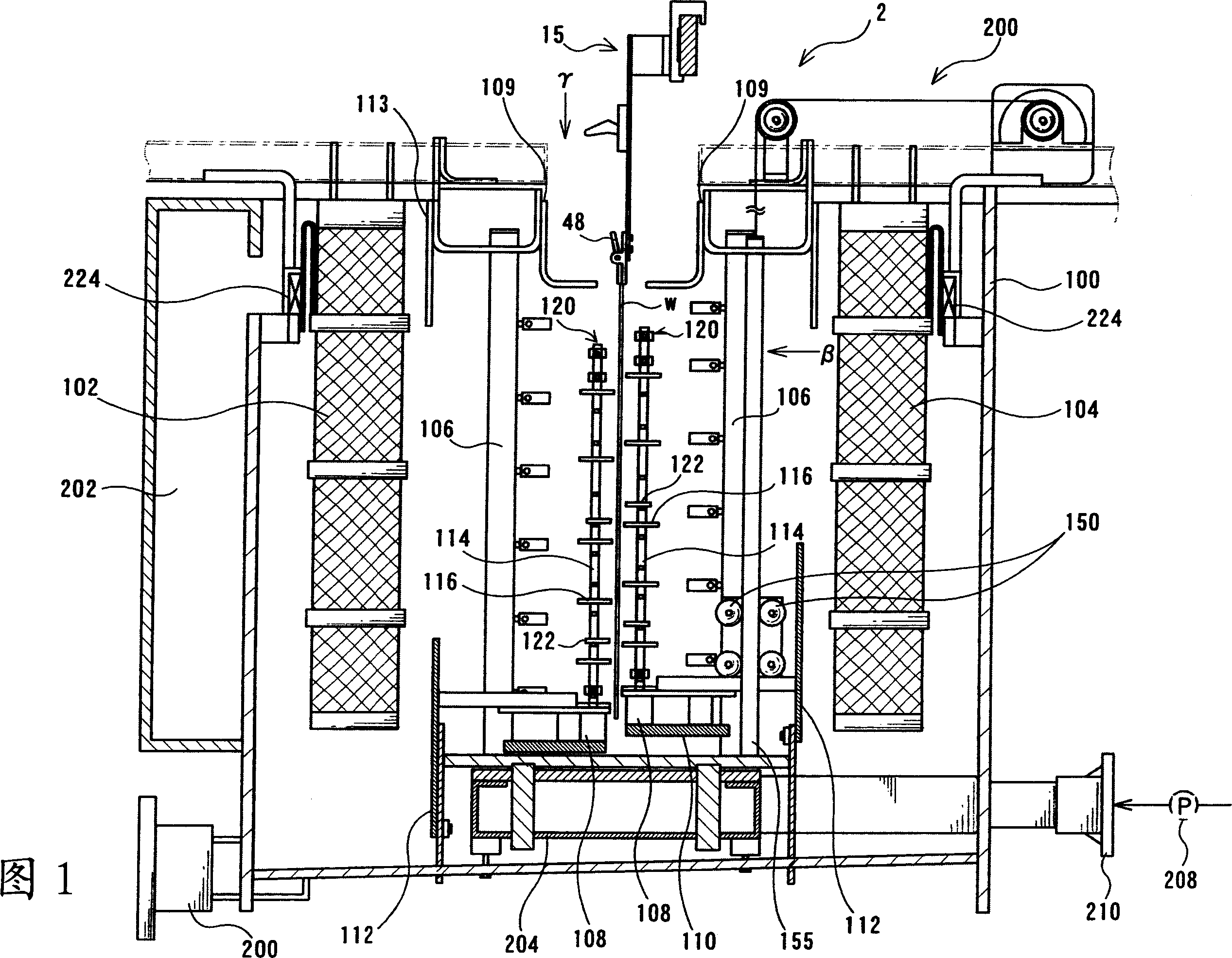
[0089] 1. Plating tank

[0090] The basic structure of the surface treatment device is the same as that shown in Fig. 14 and Fig. 15 . FIG. 14 is a plan view of the surface treatment device 300 viewed from above. FIG. 15 is a side view of the surface treatment device 300 shown in FIG. 14 viewed from the α direction.

[0091] As shown in FIGS. 14 and 15 , the surface treatment apparatus 300 has guide rails 10 to 13 for transporting a transport hanger 15 for holding a plate-shaped workpiece W such as a printed circuit board, and is provided along these guide rails. There are: pretreatment tank 1 for electroplating pretreatment process; electroplating tank 2 for electroplating process; recovery tank 3 and water washing tank 4 for electroplating post-treatment process; used for disassembly of plate-shaped workpiece W The unloading section 5; the stripping tank 6 for carrying out the peeling process (hanger return process) of the plating layer attached to the transport hanger 15 ...


PUM

PropertyMeasurementUnit
thicknessaaaaaaaaaa

Abstract

Provides a plating tank that can transport platy work securely without causing abrasion and attain uniform plating quality and uniform plating film thickness. The shields are comprised of four shielding plates (108, 109, 112, and 113) on upper part and lower part of the thin plate board as follows. The restrict roller (304) is comprised of the roller stand body (120) which reaches until nearly upper end area's height of thin plate board and stood on upper face of the lower shielding plates (108), and the work-end deviation preventing member (122).

Description

[0001] The scope of the claims of Japanese Patent Application No. 2005-323028, the description, the drawings, and the contents of the abstract are incorporated into this application. technical field [0002] The present invention relates to a technique for electroplating plate-shaped workpieces such as printed circuit boards in surface treatment equipment such as electroplating equipment. Background technique [0003] In conventional surface treatment equipment (plating equipment for printed circuit boards), the plate-shaped workpiece W is fixedly mounted on a stand so that the plate-shaped workpiece W does not shake, and the surface treatment is carried out while conveying the stand. deal with. However, mounting the plate-shaped workpiece W on a stand is a troublesome operation, and since the load applied to the device is large, resulting in an increase in size of the device, a stand-less surface treatment device has been proposed. [0004] Such a standless surface treatme...

Claims


Application Information

Patent Timeline
Patent Type & Authority Applications(China)
IPC IPC(8): C25D17/00C25D17/06C25D5/08C25D7/00H05K3/18
CPCC25D17/008C25D17/00H05K3/241C25D17/06C25D17/02
Inventor 奥田朋士水本纯司木村豊大村泰基
Owner C UYEMURA & CO LTD
Why Eureka
Try Eureka