Supercharge Your Innovation With Domain-Expert AI Agents!

High frequency sampling device

A technology of high-frequency sampling and differential amplifier, which is applied in real-time pulse transmission devices, automatic power control, pulse processing, etc., and can solve problems such as difficult to achieve high-frequency sampling, small scope of application, and difficulties

Inactive Publication Date: 2010-05-26
江苏北方湖光光电有限公司
View PDF3 Cites 0 Cited by
  • Summary
  • Abstract
  • Description
  • Claims
  • Application Information

AI Technical Summary

Problems solved by technology

However, it is very difficult to generate narrow pulses that are stable at high frequencies and have a pulse width less than 1 ns or even tens of ps and have a certain amplitude.
Therefore, the above-mentioned sampling circuit can only perform low-frequency sampling, it is difficult to realize high-frequency sampling, and the scope of application is small

Method used


Image

  • High frequency sampling device
  • High frequency sampling device

Examples


Embodiment Construction

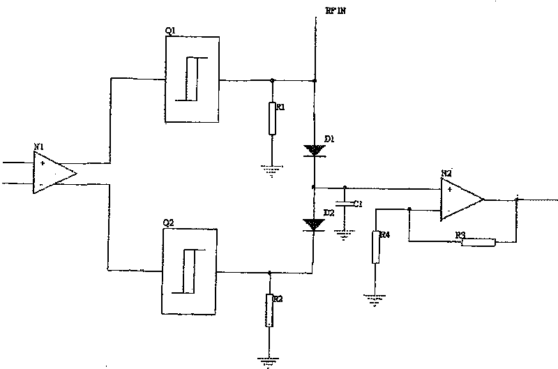
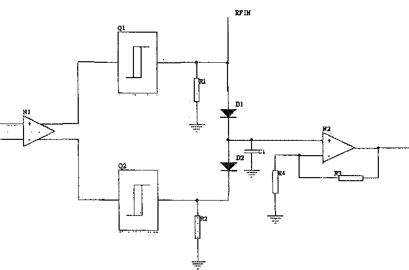
[0010] Such as figure 1 As shown, the high-frequency sampling device of the present invention includes a differential amplifier N1, a comparison amplifier N2, two Schmitt triggers Q1, Q2 and two diodes D1, D2. The input terminal of the differential amplifier N1 is the input terminal of the sampling clock, and its two differential output terminals are connected to the input terminals of the Schmitt trigger Q1 and the Schmitt trigger Q2 respectively. The output of the Schmitt trigger Q1 is connected to the positive pole of the diode D1, and the output terminal of the Schmitt trigger Q2 is connected to the negative pole of the diode D2. The cathode of the diode D1 and the anode of the diode D2 are connected in series. Resistors R1 and R2 are respectively connected between the anode of the diode D1 and the ground, and between the cathode of the diode D2 and the ground. When working, the radio frequency signal RFIN is connected to the anode of the diode D1. The positive input te...


PUM


Abstract

The invention relates to a high-frequency sampling circuit, wherein it comprises differential amplifier, comparing amplifier, two Schmitt triggers and two diodes; two differential outputs of differential amplifier are connected to the inputs of Schmitt triggers; two diodes are connected, while their disconnected ends are connected to the outputs of two Schmitt triggers, and there is resistance between disconnected end and ground; the connected ends of two diodes are connected to the positive input of comparing amplifier; the passive input of comparing amplifier has resistance with output and ground; the positive input of comparing amplifier has capacitor with ground. The invention can realize high-frequency and low-frequency sampling.

Description

technical field [0001] The invention relates to an electronic circuit. Specifically, it is a high-frequency sampling device for sampling signals in the signal processing process of radio communication and radio detection. Background technique [0002] In the signal processing process of radio communication and radio detection, signal sampling is an extremely important and indispensable link. Without successfully sampling the signal, the entire system cannot function. [0003] Traditional sampling circuits are mostly gate circuits. This gate circuit is composed of four diodes connected end to end, and the input signal is sampled by a sufficiently large differential narrow pulse clock. The sampling ability of this sampling circuit depends on the width of the extremely narrow pulse, that is, the width of the narrow pulse should be much smaller than the period of the signal being sampled. If the frequency of the collected signal is increased, the required pulse width will be...

Claims


Application Information

Patent Timeline
Patent Type & Authority Patents(China)
IPC IPC(8): H03K5/00H03K5/153H03K5/1534H03K5/22H03L7/00G06F1/06
Inventor 叶青青
Owner 江苏北方湖光光电有限公司
Features
  • R&D
  • Intellectual Property
  • Life Sciences
  • Materials
  • Tech Scout
  • Unparalleled Data Quality
  • Higher Quality Content
  • 60% Fewer Hallucinations
Learn More