Ultrashort laser pulse multipath delay synchronous testing method
A technology for multi-channel delay and synchronization testing, which can be used in instruments and other directions to solve problems such as low synchronization accuracy
- Summary
- Abstract
- Description
- Claims
- Application Information
AI Technical Summary
Problems solved by technology
Method used
Image
Examples
Embodiment 1
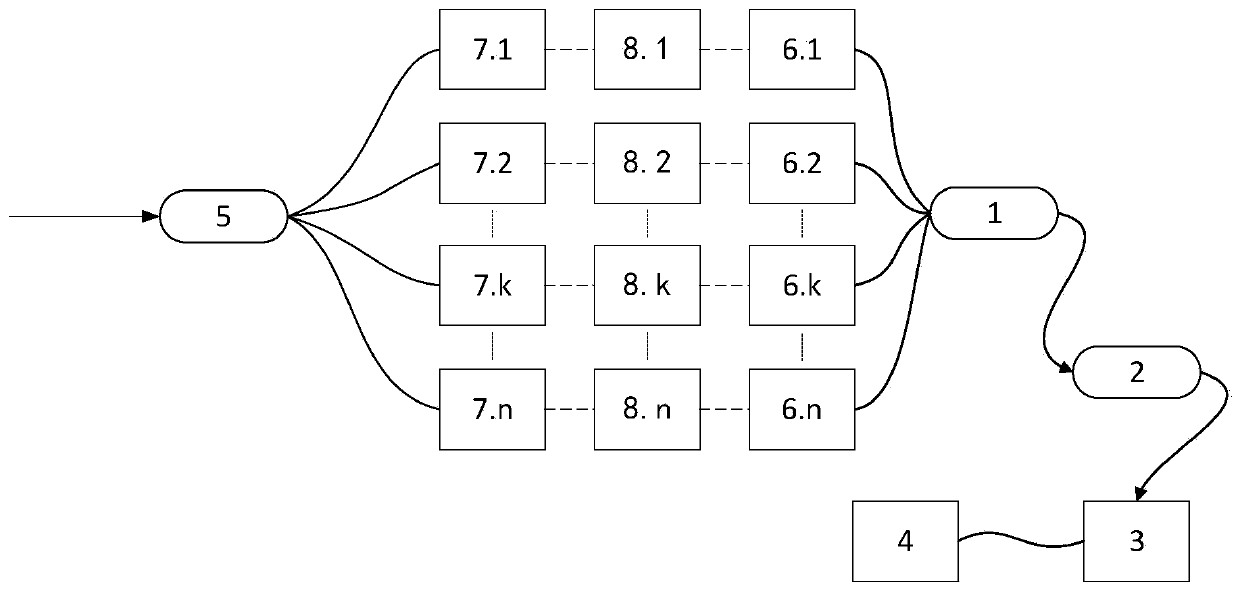
[0082] Such as image 3 As shown, the schematic diagram of Embodiment 1 of the ultrashort pulse time-delay synchronous detection and control device of the present invention, in the figure, a 50:50 polarization maintaining beam combiner 1, an online polarizer 2, a spectrometer 3, a data processing PC4, and a 50:50 polarization maintaining beam splitter 5, calibration delayer 6.1, calibration fiber 6.2, mode-locked laser 14. 50:50 polarization maintaining beam combiner 1, 50:50 polarization maintaining beam splitter 5, and the pigtail length of calibration delayer 6.1 are about 1m. The entire setup uses polarization maintaining fiber. The central wavelength of the mode-locked laser 14 is about 1563nm, and the spectral half-maximum width is about 6nm. The length of the calibration optical fiber 6.2 is about 2m, so that the delay difference between the two paths is small, which is in line with the use of the present invention. The delay adjustment range of calibration delayer 6...
Embodiment 2
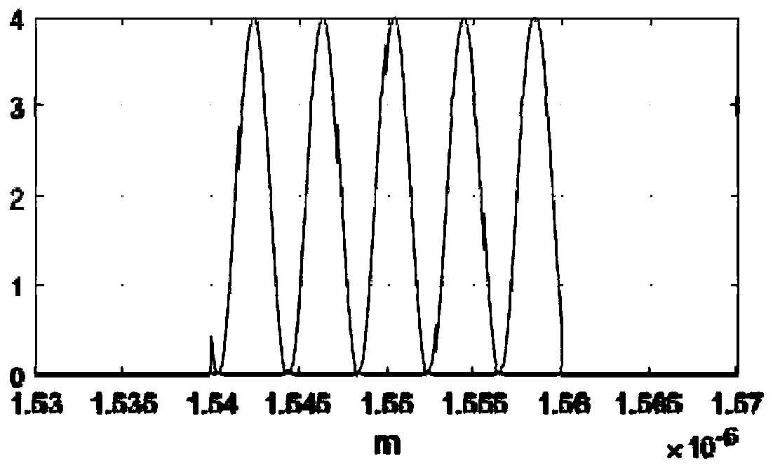
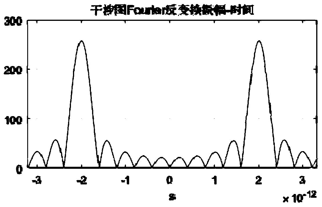
[0087] Such as Figure 6 As shown, without connecting the synchronous delayers 7.1, 7.2, 7.3, 7.4 first, the 14 pulses of the mode-locked laser pass through the beam splitter 5 and enter the calibration delayers 6.1, 6.2, 6.3, 6.4, calibration delayers 6.1, 6.2, 6.3, 6.4 Connect the beam combiner 1, the ultra-short laser beams pass through the polarizer 2 and then enter the spectrometer 3. The data accuracy is 0.13nm, and the number of points after expansion is 2 18 . Control the calibration delays 6.1, 6.2, 6.3, 6.4 and adjust the delays from small to large, and the delay difference between the calibration delay 6.1 and the calibration delay 6.4 is greater than that of the calibration delay 6.1 and the calibration delay 6.3 Twice of the delay difference; the spectrometer 3 image data is imported into PC4, and the data is processed as in step 2, the result is as shown in Figure 7 (a), the delay between calibration delayer 6.1 and calibration delayer 6.2,6.3,6.4 The time dif...
PUM
 Abstract
Description
Claims
Application Information
 - R&D
- Intellectual Property
- Life Sciences
- Materials
- Tech Scout
- Unparalleled Data Quality
- Higher Quality Content
- 60% Fewer Hallucinations
Browse by: Latest US Patents, China's latest patents, Technical Efficacy Thesaurus, Application Domain, Technology Topic, Popular Technical Reports.
© 2025 PatSnap. All rights reserved.Legal|Privacy policy|Modern Slavery Act Transparency Statement|Sitemap|About US| Contact US: help@patsnap.com


