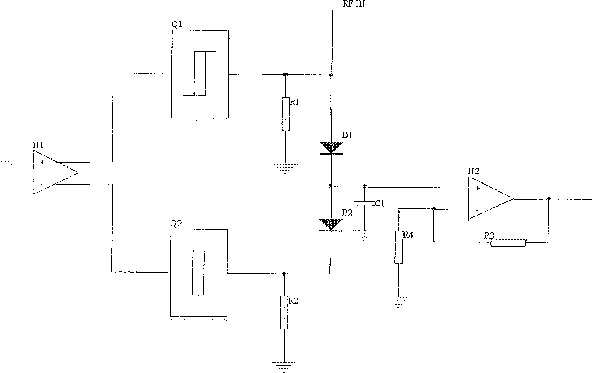
High frequency sampling circuit
A high-frequency sampling and circuit technology, applied in multiple input and output pulse circuits, electrical components, automatic control of power, etc., can solve problems such as small application range, difficulty, and difficulty in realizing high-frequency sampling.
- Summary
- Abstract
- Description
- Claims
- Application Information
AI Technical Summary
Problems solved by technology
Method used
Image
Examples
Embodiment Construction
[0010] As shown in the drawings, the high-frequency sampling circuit of the present invention includes a differential amplifier N1, a comparison amplifier N2, two Schmitt triggers Q1, Q2 and two diodes D1, D2. The input terminal of the differential amplifier N1 is the input terminal of the sampling clock, and its two differential output terminals are connected to the input terminals of the Schmitt trigger Q1 and the Schmitt trigger Q2 respectively. The output of the Schmitt trigger Q1 is connected to the positive pole of the diode D1, and the output terminal of the Schmitt trigger Q2 is connected to the negative pole of the diode D2. The cathode of the diode D1 and the anode of the diode D2 are connected in series. Resistors R1 and R2 are respectively connected between the anode of the diode D1 and the ground, and between the cathode of the diode D2 and the ground. When working, the radio frequency signal RFIN is connected to the anode of the diode D1. The positive input ter...
PUM
 Abstract
Description
Claims
Application Information
 - R&D
- Intellectual Property
- Life Sciences
- Materials
- Tech Scout
- Unparalleled Data Quality
- Higher Quality Content
- 60% Fewer Hallucinations
Browse by: Latest US Patents, China's latest patents, Technical Efficacy Thesaurus, Application Domain, Technology Topic, Popular Technical Reports.
© 2025 PatSnap. All rights reserved.Legal|Privacy policy|Modern Slavery Act Transparency Statement|Sitemap|About US| Contact US: help@patsnap.com

