Floating ball valve

A ball float valve and ball float technology, applied in the field of ball float valves, can solve problems such as increasing the volume of the ball float, impact, and the volume of the ball float should not be too large

Active Publication Date: 2007-06-06
杨召泽
View PDF0 Cites 6 Cited by
  • Summary
  • Abstract
  • Description
  • Claims
  • Application Information

AI Technical Summary

Problems solved by technology

This kind of floating ball valve, because the valve core is directly driven by the lever, limited by the volume of the valve core, the distance from the point where the lever acts on the valve core to the lever fulcrum is relatively long. To meet the requirements, the length of the lever must be increased or the volume of the floating ball must be increased. Due to the limitation of the installation position, the length of the lever cannot be too long, and the volume of the floating ball cannot be too large. This will inevitably affect the leverage The force on the spool prevents the spool from fully closing the valve, resulting in water leakage, especially when the water pressure is high, the above-mentioned bad situations are more likely to occur

Method used


Image

  • Floating ball valve
  • Floating ball valve

Examples


Embodiment Construction

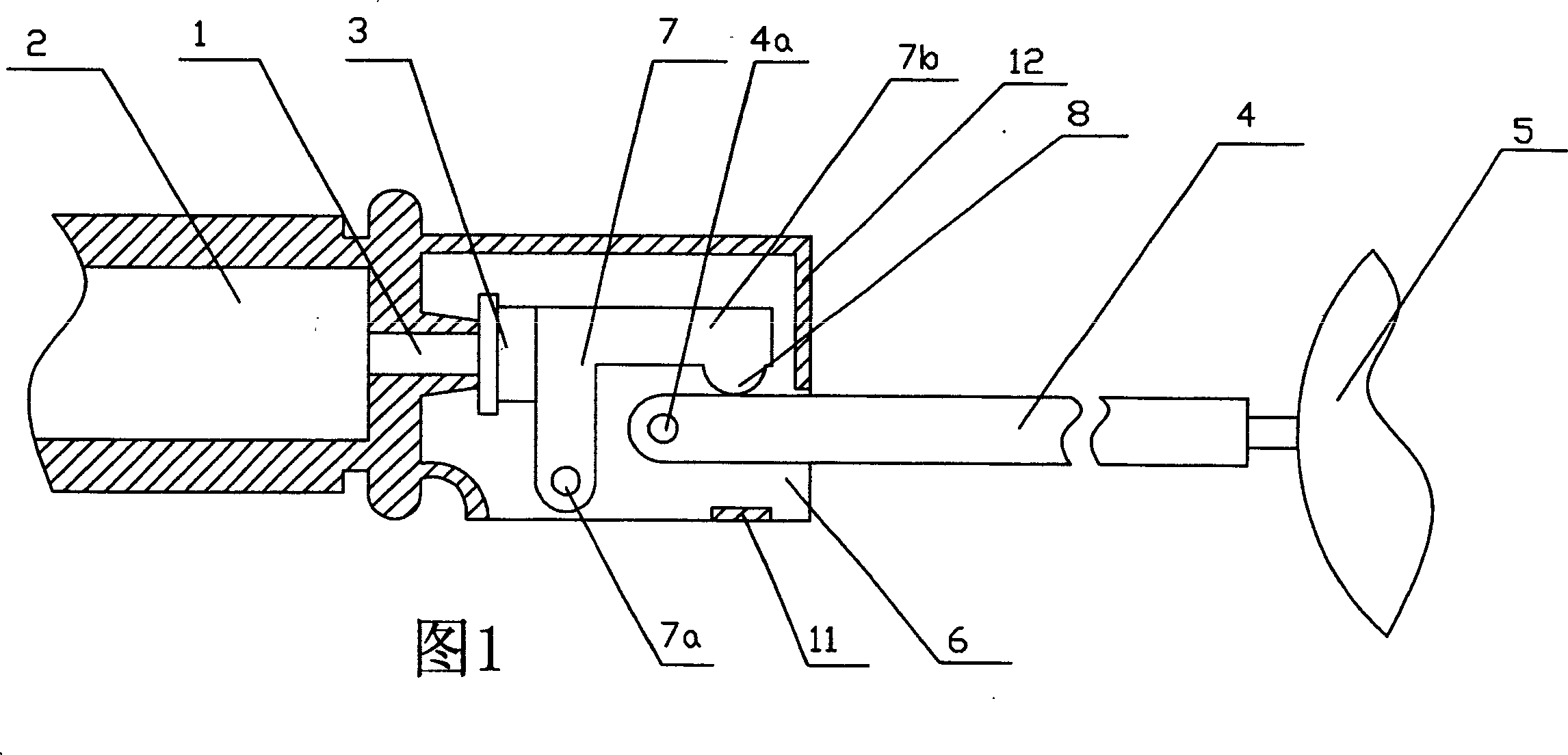
[0008] Now in conjunction with accompanying drawing and embodiment the present invention is described in further detail:

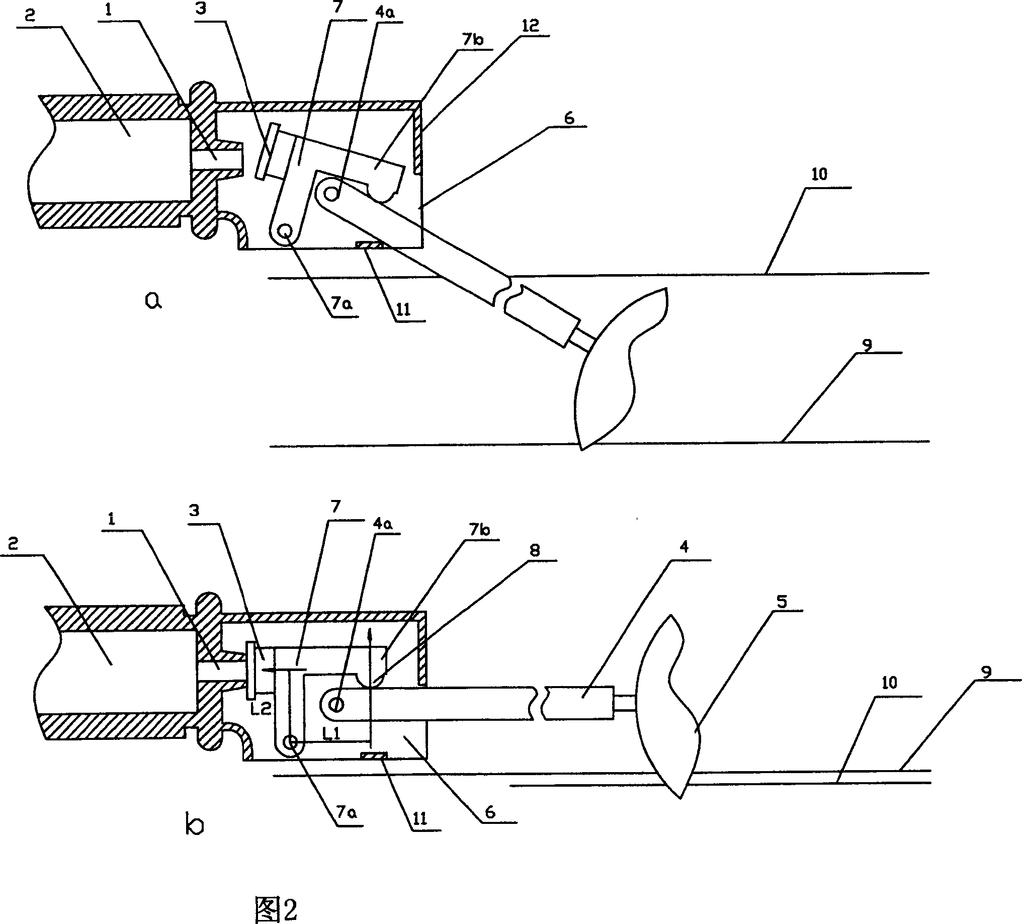
[0009] As shown in Figure 1, the present invention includes a valve body 2 with a valve 1, a valve core 3 arranged in front of the valve 1, a lever 4 that drives the action of the valve 1, and a floating ball 5 arranged at the end of the lever 4. There is a seat 6 on the valve body 2 in front of the valve 1, the valve core 3 is connected with an L-shaped rod 7, and one end 7a of the L-shaped rod 7 is rotatably connected to the seat 6 below the valve 1, and the fulcrum of the lever 4 4a is rotated and articulated on the seat 6 in front of the L-shaped bar 7 live joints 7a, and the free end 7b of the L-shaped bar 7 rides on the lever 4.

[0010] In order to prevent the fulcrum 4a of the lever 4 from hindering the L-shaped rod 7 from driving the spool 3 to leave the valve 1, a protrusion 8 which rides on the lever 4 is provided below the free end 7b of the L-...


PUM


Abstract

A float valve comprises a valve body, a spool disposed in the front of the valve, a lever driving the valve to act and a ball set at the end of the lever. On the valve body in the front of the valve is disposed a seat and on the spool is connected an L-shaped rod, whose one end rotates and is loose jointed on the seat under the valve. The support of the lever rotates and is loose jointed on the seat in front of the L-shaped rod loose joint and the free end of the L-shaped rod is put over the lever.

Description

Technical field: [0001] The invention relates to a ball float valve. Background technique: [0002] In the existing floating ball valve, the floating ball and the valve core are connected by a lever. When the water level reaches a certain height, the floating ball drives the lever to start acting on the valve core, making the valve core close to the valve, and finally at the water level. When the preset height is reached, the valve is closed. This kind of floating ball valve, because the valve core is directly driven by the lever, limited by the volume of the valve core, the distance from the point where the lever acts on the valve core to the lever fulcrum is relatively long. To meet the requirements, the length of the lever must be increased or the volume of the floating ball must be increased. Due to the limitation of the installation position, the length of the lever cannot be too long, and the volume of the floating ball cannot be too large. This will inevitably affect...

Claims


Application Information

Patent Timeline
Patent Type & Authority Applications(China)
IPC IPC(8): F16K1/20F16K31/24
Inventor 杨召泽
Owner 杨召泽
Why Eureka
Try Eureka