
Piston-driven straight-through type pressure and flow regulating valve

A piston-driven, straight-through technology, applied in the valve's device for absorbing fluid energy, valve details, safety valve, etc., can solve problems such as easy generation of turbulent flow, unsmooth fluid flow, and easy cavitation.

Pending Publication Date: 2020-10-20
TIANJIN TANGGU NO 1 VALVE FACTORY
View PDF0 Cites 4 Cited by
  • Summary
  • Abstract
  • Description
  • Claims
  • Application Information

AI Technical Summary

Problems solved by technology

During the use of the existing pressure reducing valve, even if it is installed in a horizontal pipeline, after the water flow enters the valve body, the direction of the water flow is changed, the fluid flow direction is very unsmooth, and the impact on the valve body and parts is relatively large , resulting in a large head loss, and prone to turbulent flow, resulting in serious pipeline vibration, and prone to cavitation

Method used

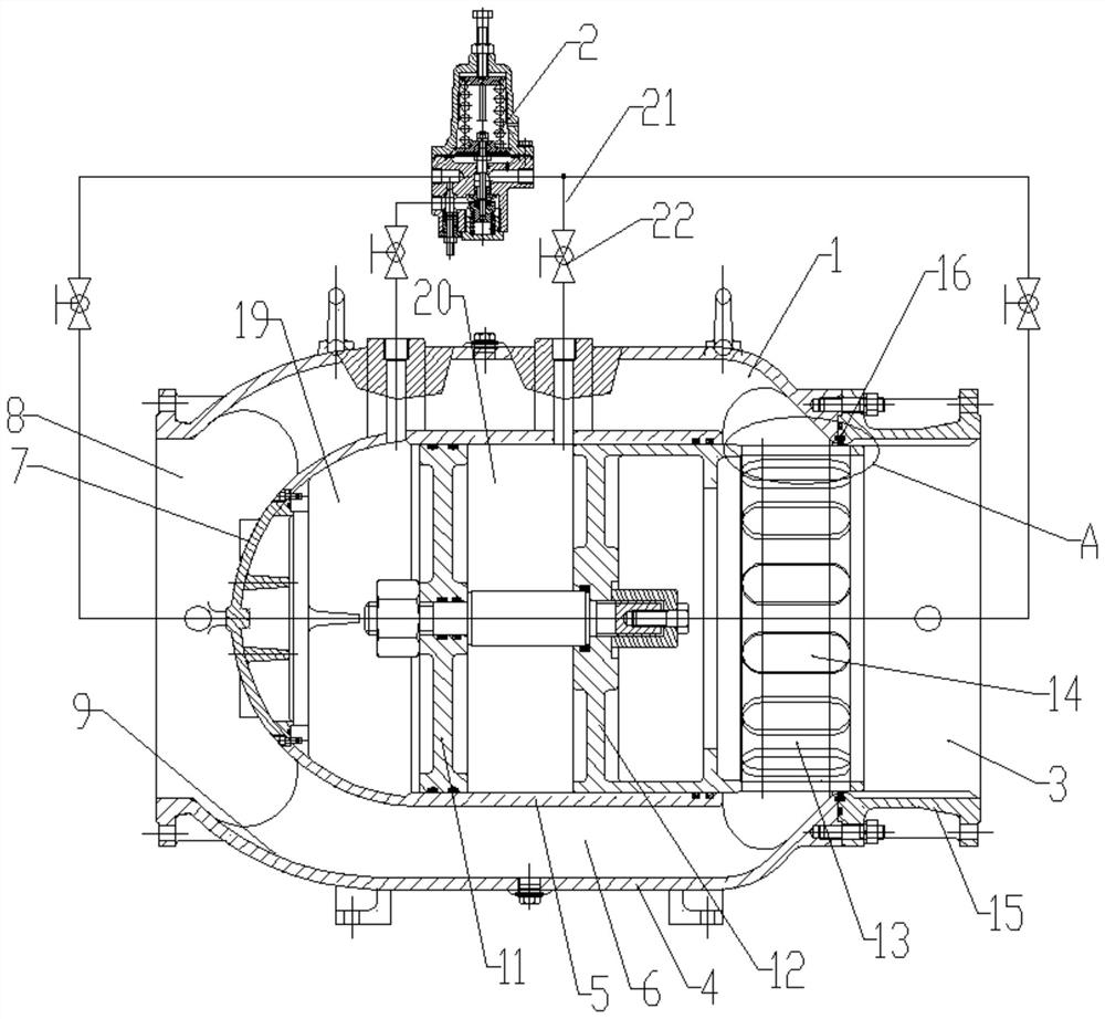
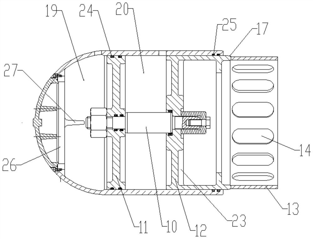
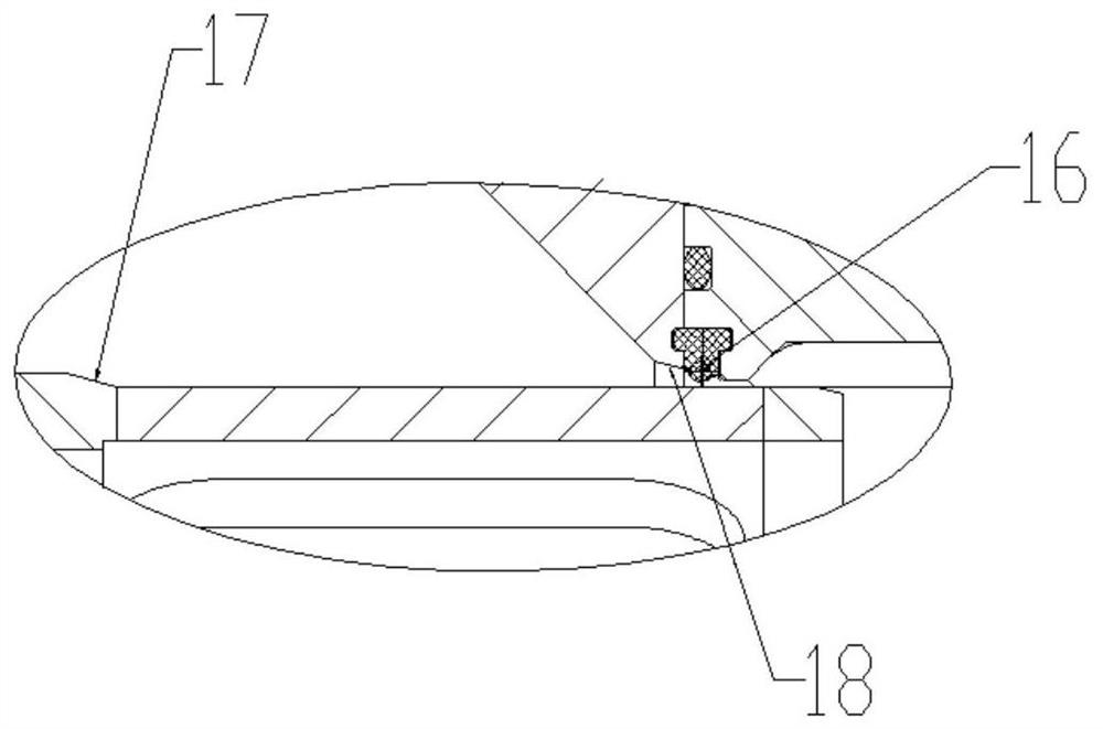

Image

  • Piston-driven straight-through type pressure and flow regulating valve
  • Piston-driven straight-through type pressure and flow regulating valve
  • Piston-driven straight-through type pressure and flow regulating valve

Examples


Embodiment Construction

[0028] It should be noted that, in the case of no conflict, the embodiments of the present invention and the features in the embodiments can be combined with each other.

[0029] In describing the present invention, it should be understood that the terms "center", "longitudinal", "transverse", "upper", "lower", "front", "rear", "left", "right", The orientations or positional relationships indicated by "vertical", "horizontal", "top", "bottom", "inner", "outer", etc. are based on the orientation or positional relationships shown in the drawings, and are only for the convenience of describing the present invention Creation and simplification of description, rather than indicating or implying that the device or element referred to must have a specific orientation, be constructed and operate in a specific orientation, and therefore should not be construed as limiting the invention. In addition, the terms "first", "second", etc. are used for descriptive purposes only, and should no...


PUM


Abstract

The invention provides a piston-driven straight-through type pressure and flow regulating valve. The piston-driven straight-through type pressure and flow regulating valve comprises a main valve and apilot valve connected with the main valve, an outer shell and an inner shell of a valve body of the main valve are coaxially arranged, a valve cavity is formed between the outer shell and the inner shell, and a driving device is installed in the inner shell in a sliding mode in the axial direction; an end cover with a spherical structure is arranged on the side, facing a first port, of the innershell; and the inner walls of the two ends of the shell are each of an arc-shaped structure, the inner diameter of each arc-shaped structure is gradually reduced from inside to outside, long grooves are formed in the axial direction of a pup joint, and the outlet side pressure of the valve body is adjusted through the length of the long grooves in a pressure reduction opening-closing piece extending into the valve cavity. A pressure reducing valve provided by the straight-through type pressure and flow regulating valve has high distribution capacity, water flow energy counteracts each other atthe arc-shaped structure at the outlet of the valve body, cavitation and vibration can be effectively avoided, and due to the fact that the pressure reducing opening and closing piece is subjected tothe effect of control pressure of the guide valve, the valve has a pressure regulating function, water head loss is very small during opening and closing, and resistance is small during complete opening; and meanwhile, the valve is closed tightly and is good in sealing performance.

Description

technical field [0001] The invention belongs to the technical field of valves, and in particular relates to a straight-through pressure-regulating and flow-regulating valve driven by a piston. Background technique [0002] The pressure reducing valve is widely used in various pipeline systems. The pressure reducing valve is a valve that reduces the inlet pressure to a certain required outlet pressure through adjustment, and relies on the energy of the medium itself to keep the outlet pressure automatically stable. During the use of the existing pressure reducing valve, even if it is installed in a horizontal pipeline, after the water flow enters the valve body, the direction of the water flow is changed, the fluid flow direction is very unsmooth, and the impact on the valve body and parts is relatively large , resulting in a large head loss, and prone to turbulent flow, resulting in serious pipeline vibration, and prone to cavitation. Therefore, it is necessary to improve t...

Claims


Application Information

Patent Timeline
IPC IPC(8): F16K17/164F16K31/363F16K47/02
CPCF16K17/164F16K31/363F16K47/02
Inventor 洪荣坤洪永金刘杰张正龙
Owner TIANJIN TANGGU NO 1 VALVE FACTORY
Learn More