Rescue robot system for fire-fighting and method thereof

A technology for rescue robots and fire, applied in the field of robots, can solve problems such as the blank of fire rescue robots, and achieve the effect of easy control

Inactive Publication Date: 2007-07-11
INST OF AUTOMATION CHINESE ACAD OF SCI
View PDF0 Cites 7 Cited by
  • Summary
  • Abstract
  • Description
  • Claims
  • Application Information

AI Technical Summary

Problems solved by technology

At present, fire extinguishing robots and reconnaissance r...

Method used


Image

  • Rescue robot system for fire-fighting and method thereof

Examples


Embodiment Construction

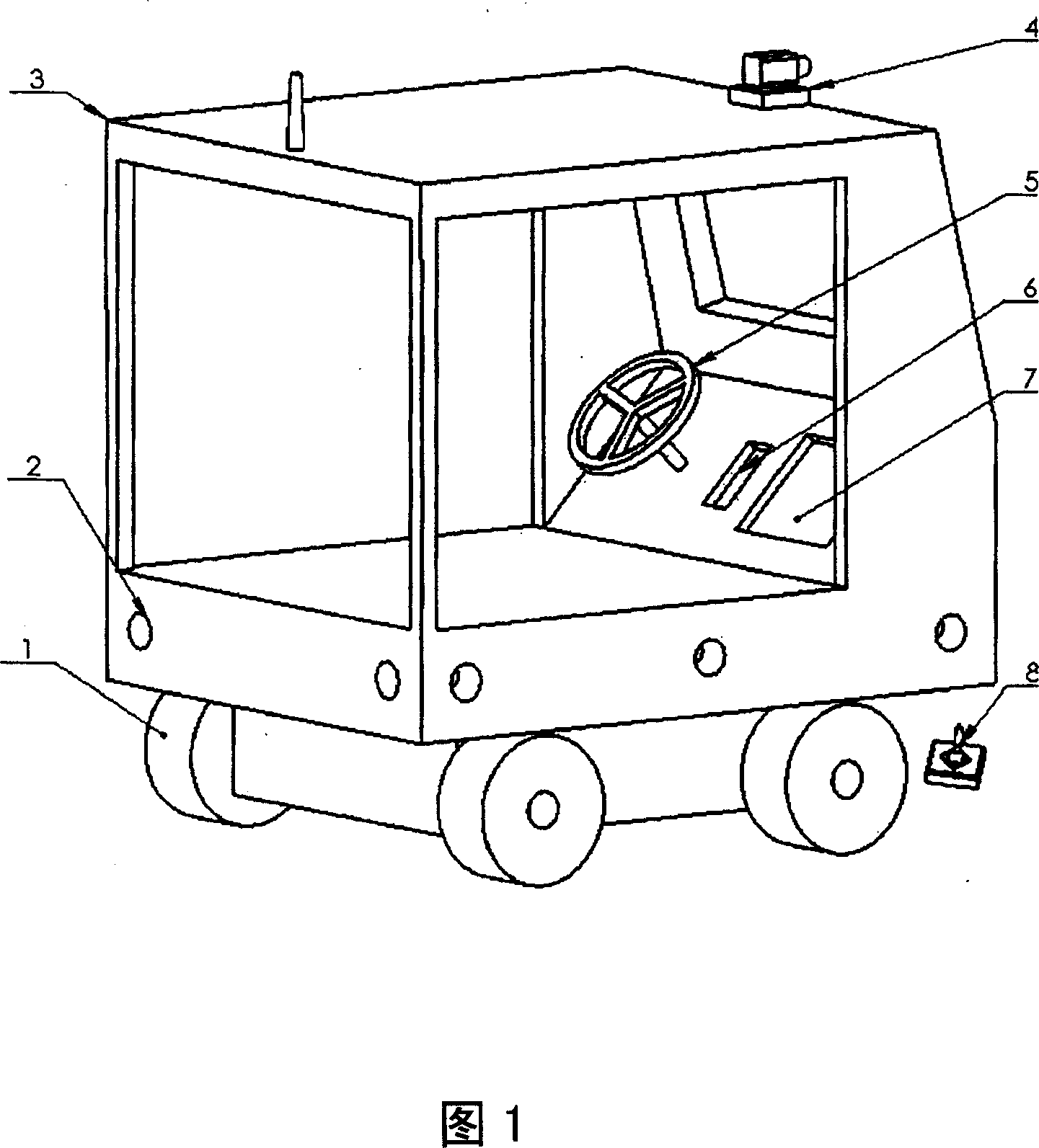
[0025] The three-dimensional structure of the fire rescue robot of the present invention is shown in FIG. 1 . The fire rescue robot system includes: a mobile vehicle body 1 , a sensing mechanism 2 and a protective cover 3 ; an image and sound localizer 4 ; a driving mechanism 5 ; an intercom 6 ; a display 7 and a wireless controller 8 . Wherein, the sensing mechanism 2, the protective cover 3, the image and sound locator 4, the driving mechanism 5, the intercom 6 and the display 7 are assembled inside or outside the mobile vehicle body 1, and the wireless controller 8 and the mobile vehicle body 1 can perform wireless communication. communication.

[0026] Each part is described below.

[0027] The mobile car body 1 is the chassis of an ordinary motor vehicle, and the main difference and key technologies lie in the protective performance, sensing performance and control performance of the robot. The mobile car body 1 is made up of wheels and a car body with certain fire-resi...


PUM


Abstract

The invention relates to a fire hazard rescue robot, which comprises movable vehicle, sensor and protective frame, image sound positioning device, driver, intercom, display and wireless controller. Remote operator can use wireless controller to move vehicle into fire site to find and rescue people; and the positioning device will transmit collected data to the remote controller, to find the people position; remote operator controls the vehicle to approach people; and the people can start the protective frame or drive the vehicle by itself, while the vehicle can be controlled by remote operator.

Description

technical field [0001] The invention belongs to the technical field of robots, in particular to a fire rescue robot system and a method thereof. Background technique [0002] In recent years, in the production process and transportation process of the petrochemical industry, the leakage of flammable, explosive and highly toxic chemicals, as well as the accidents of burning and explosion have increased frequently. In order to avoid casualties and huge property losses in the fire process, it has been It is clear that the fire robot is the main force in this dangerous situation. At present, fire extinguishing robots and reconnaissance robots have been developed, but fire rescue robots are still blank. Contents of the invention [0003] The purpose of the present invention is to develop a fire rescue robot, which can replace firefighters to go deep into the fire scene to search and rescue people in distress in dangerous situations such as leakage of flammable, explosive and h...

Claims


Application Information

Patent Timeline
IPC IPC(8): A62C27/00
Inventor 赵冬斌易建强
Owner INST OF AUTOMATION CHINESE ACAD OF SCI
Why Eureka
Try Eureka