Integrated security network

a security network and integrated technology, applied in the field of security monitoring, can solve the problems of requiring a one-way communication scheme, presenting an array of other problems, and requiring cms to distinguish a real intruder from a false alarm, so as to achieve more efficient video archiving

Active Publication Date: 2018-06-19
SECURENET TECH
View PDF16 Cites 145 Cited by
  • Summary
  • Abstract
  • Description
  • Claims
  • Application Information

AI Technical Summary

Benefits of technology

[0011]It is another object to provide an architecture as above with video enhancements, including an operator server adapted for video data networking in an integrated security network that authenticates users, establishes a peer-to-peer data connection between a designated video camera and remote user computers such that users can receive a live video stream and / or archive video. In this latter regard, it is another object to dynamically generate destination paths comprising a camera ID and the date and time and archive video data directly to the generated path so as to negate the subsequent moving of the video data.
[0016]In another aspect, an improved process for remotely accessing video is disclosed including video peer-to-peer handoffs of live video from the operator server, and more efficient video archiving.

Problems solved by technology

This inherently compels a one-way communication scheme, control panel-to-receiver to CMS.
Moreover, the occurrence of an alarm provides no indication of its cause and so the CMS has no means to distinguish a real intruder from a false alarm.
The one-way communication scheme also presents am array of other issues in case of network failure, disablement of the control panel, etc.
However, a problem with such arrangements is that the alarm control panel may be disabled by an intruder prior to being able to send the alarm signal.
For example, the home security system may be physically smashed or removed.
However, concealment does not solve the problem for intruders having knowledge of the security system installation.
However, battery backup systems are not failsafe and may themselves be disconnected by the intruder.
Furthermore, the communication interface of the alarm control panel may be disabled wherein, for example, the intruder may disconnect the communication interface of the alarm control panel, utilize cellular jamming devices and the like.
This creates its own set of limitations.

Method used


Image

  • Integrated security network
  • Integrated security network
  • Integrated security network

Examples


Embodiment Construction

[0028]For the purposes of promoting an understanding of the principles of the invention, reference will now be made to the exemplary embodiment illustrated in the drawings and described below. The embodiment disclosed is not intended to be exhaustive or limit the invention to the precise form disclosed in the following detailed description. Rather, the embodiment is chosen and described so that others skilled in the art may utilize its teachings. It will be understood that no limitation of the scope of the invention is thereby intended. The invention includes any alterations and modifications in the illustrated device, the methods of operation, and further applications of the principles of the invention as would normally occur to one skilled in the art to which the invention relates.

[0029]The present invention includes both the system architecture and hardware as well as the computer processes.

[0030]As herein defined the term “Automation Server” means a software application that exp...


PUM


Abstract

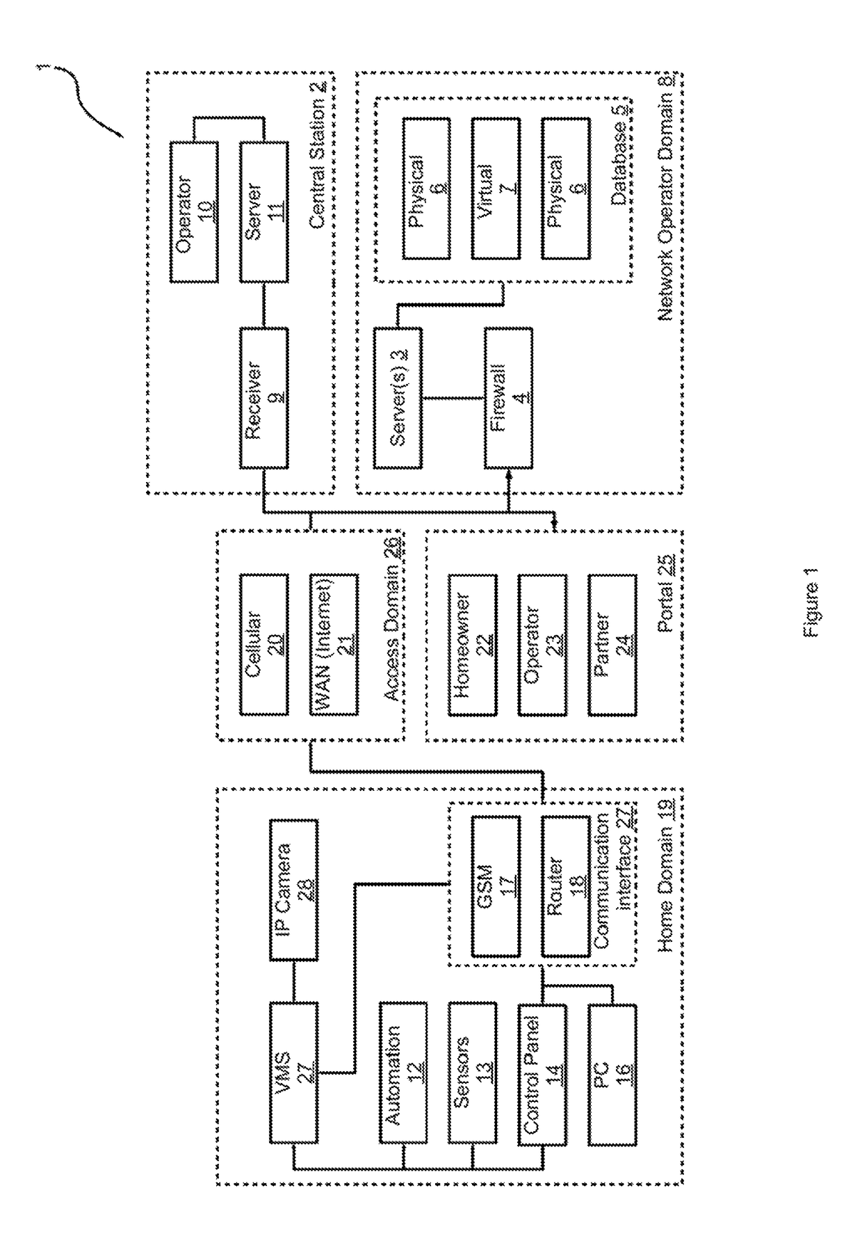
A security system architecture and method of operation that combines a local security network with control panel and sensors, a central monitoring station (CMS), and a separate operator computer server that provides a web portal for both the homeowner and CMS, that maintains a persistent connection between the control panel and CMS allowing failsafe dual-path signaling. This dual-path signaling technique is extended to provide an effective “smash and grab alarm”, and various approaches to dual-path signal management are disclosed including handshaking, persistent domain monitoring, relayed Operator 3-to-CMS signaling, etc. Improved processes for remotely accessing video are also disclosed along with an improved process for remote control panel configuration, and control panel interfacing with home automation appliances.

Description

CROSS-REFERENCE TO RELATED APPLICATIONS[0001]The present application derives priority from Australian provisional patent application number 2015903140 filed 5 Aug. 2015, Australian provisional patent application number 2015903139 filed 5 Aug. 2015, Australian provisional patent application number 2015903138 filed 5 Aug. 2015, Australian provisional patent application number 2015903137 filed 5 Aug. 2015, Australian provisional patent application number 2015903136 filed 5 Aug. 2015, Australian provisional patent application number 2015903135 filed 5 Aug. 2015, Australian provisional patent application number 2015903134 filed 5 Aug. 2015, Australian provisional patent application number 2015903133 filed 5 Aug. 2015, Australian provisional patent application number 2015903132 filed 5 Aug. 2015, and Australian provisional patent application number 2015903131, filed 5 Aug. 2015.BACKGROUND OF THE INVENTION[0002]1. Field of the Invention[0003]The present invention relates generally to secur...

Claims


Application Information

Patent Timeline
Patent Type & Authority Patents(United States)
IPC IPC(8): G08B13/196G08B25/14G08B25/00H04L9/00G08B29/04
CPCG08B13/19656G08B25/002G08B25/14H04L9/00G08B13/19665G08B29/046H04L9/0819
Inventor WILSON, DAVID STUARTWILSON, ANDREW
Owner SECURENET TECH
Why Eureka
Try Eureka