Scissor lift platform

a technology of a platform and a lift, which is applied in the direction of lifting devices, vehicle with a raised platform, loading/unloading, etc., can solve the problems of difficult to move such lifts from one vehicle to another, complex devices that require modification of the vehicle frame and electrical system, and low practical limit of lift capacity in the prior ar

Inactive Publication Date: 2018-07-10
STRONG WATER LLC
View PDF24 Cites 8 Cited by
  • Summary
  • Abstract
  • Description
  • Claims
  • Application Information

AI Technical Summary

Problems solved by technology

Prior art lift systems were often complex devices that required modification to the vehicle frame and electrical system.
Because of this, it was generally not practical to move such lifts from one vehicle to another.
This placed a fairly low practical limit on their lift capacity.
Further, prior art lifts generally could not function with a vehicle tail gate in place.
Recent studies suggest that removal of the tail gate harms fuel efficiency.

Method used


Image

  • Scissor lift platform
  • Scissor lift platform
  • Scissor lift platform

Examples


Embodiment Construction

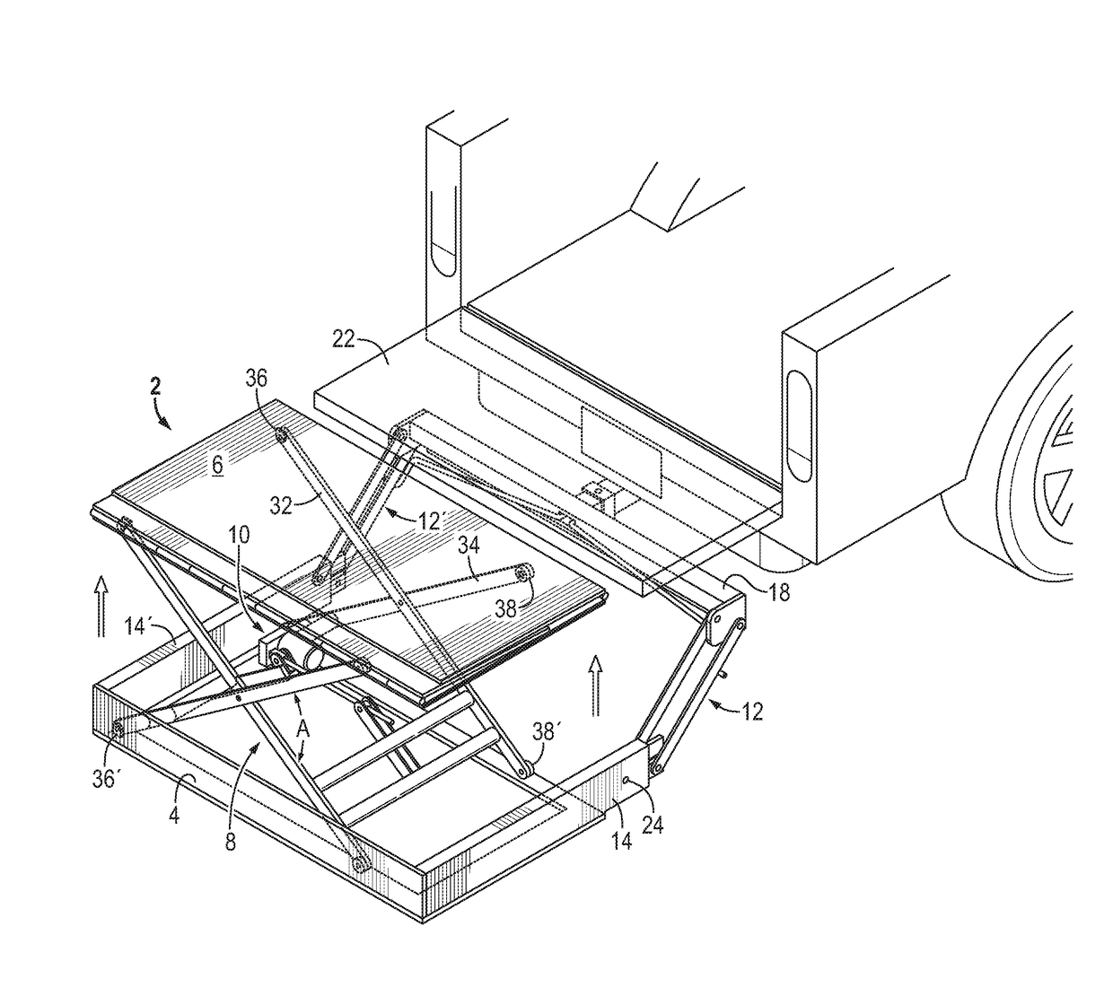
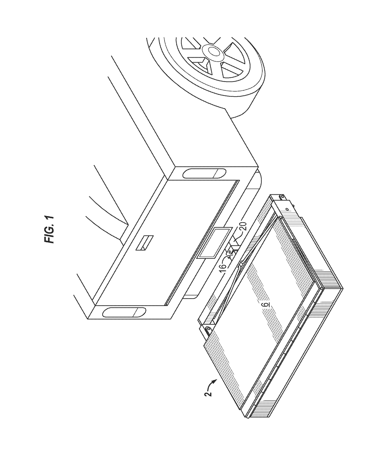
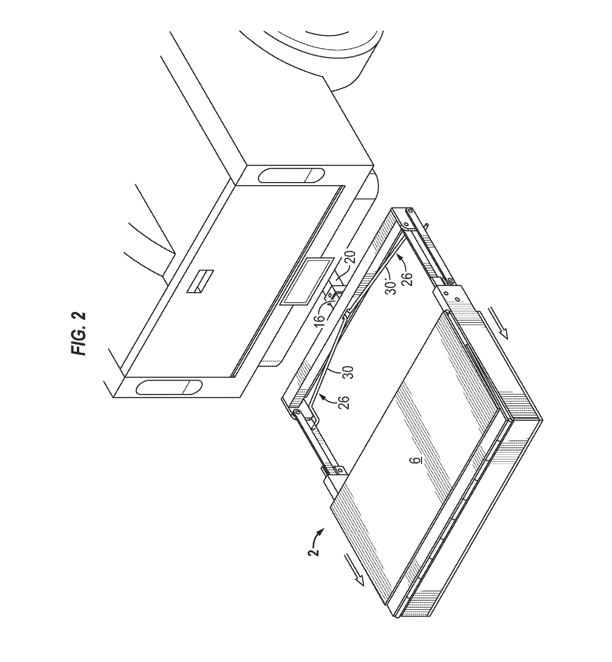
[0013]With reference to FIG. 4, a cargo lift 2 according to one embodiment of the invention comprises a frame 4, a platform 6, a scissor lift mechanism 8, an actuator 10, a pair of pivot mechanisms 12, 12′, a pair of sliding guide members 14, 14′, a probe connector 16, and a cross bar 18. The scissor lift mechanism is positioned between the frame and the platform and is provided with the actuator. The pair of pivot mechanisms raises and lowers the frame between ground level and receiver hitch level while maintaining the platform in a horizontal position. The pair of sliding guide members extends alongside the frame and attach the frame to the pivot mechanisms. The probe connector is for a receiver hitch 20 for carrying the cargo lift by a vehicle. The cross-bar is for attaching the pair of pivot mechanisms to the probe connector.

[0014]The pair of sliding guide members slides back and forth over the pivot mechanisms to adjust distance between the platform and the cross-bar. This perm...


PUM


Abstract

A cargo lift for receipt by a receiver hitch according to one embodiment of the invention comprises a frame, a platform, a scissor lift mechanism, an actuator, a pair of pivot mechanisms, a pair of sliding guide members, a probe connector, and a cross bar. The scissor lift mechanism is positioned between the frame and the platform and is provided with the actuator. The pair of pivot mechanisms raises and lower the frame between ground level and receiver hitch level while maintaining the platform in a horizontal position. The pair of sliding guide members extends alongside the frame and attaches the frame to the pivot mechanisms. The probe connector is for a receiver hitch for carrying the cargo lift by a vehicle. The cross-bar is for attaching the pair of pivot mechanisms to the probe connector.

Description

BACKGROUND OF THE INVENTION[0001]The invention relates generally to a cargo lift system for a motor vehicle and is especially well adapted for deployment on pickup trucks.[0002]Prior art lift systems were often complex devices that required modification to the vehicle frame and electrical system. Because of this, it was generally not practical to move such lifts from one vehicle to another. An easily movable lift would be desirable.[0003]Also, prior art lifts generally relied solely upon the vehicle for support. This placed a fairly low practical limit on their lift capacity. A more robust lift design is needed.[0004]Further, prior art lifts generally could not function with a vehicle tail gate in place. Recent studies suggest that removal of the tail gate harms fuel efficiency. A lift that permits the vehicle tail gate to remain in position would be more economical to use.[0005]It is an object of the invention to provide a vehicle cargo lift that overcomes the above noted deficienc...

Claims


Application Information

Patent Timeline
Patent Type & Authority Patents(United States)
IPC IPC(8): B60P1/44B66F7/06B65G69/30
CPCB60P1/4414B60P1/4492B60P1/4485B66F7/065B66F7/0641B65G69/30B60P1/44
Inventor MURPHY, MICHAELLEBLANC, ERICMURPHY, LINDA JACOBY
Owner STRONG WATER LLC
Why Eureka
Try Eureka