Drained fluid evacuation stub for a propulsion assembly

a technology for drained fluid and propulsion assembly, which is applied in the direction of fluid pressure measurement, machines/engines, instruments, etc., can solve the problems of limited volume of retention box and unsatisfactory solution, and achieve the effect of increasing the available control pressure and gaining compactness

Active Publication Date: 2018-07-10
SN DETUDE & DE CONSTR DE MOTEURS DAVIATION S N E C M A
View PDF37 Cites 10 Cited by
  • Summary
  • Abstract
  • Description
  • Claims
  • Application Information

AI Technical Summary

Benefits of technology

[0009]The invention is particularly advantageous since it makes it possible to use a pressure difference such as the external dynamic pressure and therefore the velocity of the aircraft to trigger the drainage of the retention stub and the discharge of fluids. This is because the dynamic pressure outside the stub varies according to the velocity of the aircraft. When the aircraft is at rest, the dynamic pressure is zero and the member is in its first position. The more the velocity of the aircraft increases, the more the dynamic pressure increases. The stub is designed so that its drainage is actuated when the dynamic pressure has reached a certain threshold, that is to say when the aircraft has reached a certain velocity in flight (the member is then in its second position). Thus the drainage of the stub is carried out in flight autonomously, which limits the risk of loss of drained fluids when the aircraft is on the ground.
[0015]The first measuring means is preferably connected to the first chamber by a duct comprising at least two parts, one of which is inclined or perpendicular with respect to the other. This limits the risk of particles liable to enter the orifice in the first pressure-measuring means reaching the first cavity and interfering with the measurement of dynamic pressure. These particles are intended to be trapped in the duct.
[0017]The NACA profile accelerates the fluid very locally, which causes a local negative pressure. Likewise, the NACA profile slows down the fluid very locally on the stop surface, which causes local overpressure. The difference in pressure between the minimum pressure point and the maximum pressure point on the profile therefore becomes greater than the dynamic pressure. For example, in the case of a theoretical NACA0018 profile, this pressure difference can be calculated as being greater than or equal to 1.6 times the dynamic pressure. This pressure difference serves to control the opening mechanism by means of application surfaces. This has the advantage of increasing the available control pressure, and therefore gaining in compactness for the same resulting force.

Problems solved by technology

The oil and fuel are drained by means of dynamic seal technologies (pumps, AGB, metering devices, actuators, etc.) not affording a perfect seal.
However, the volume of the retention box is limited (intentional limitation of the volume in order to limit the space requirement in the engine environment).
However, this solution is not entirely satisfactory since, in the absence of a lack of command, the retention box is not emptied and fluids may be discharged from the box through its overflow when the aircraft is on the ground.

Method used


Image

  • Drained fluid evacuation stub for a propulsion assembly
  • Drained fluid evacuation stub for a propulsion assembly
  • Drained fluid evacuation stub for a propulsion assembly

Examples


Embodiment Construction

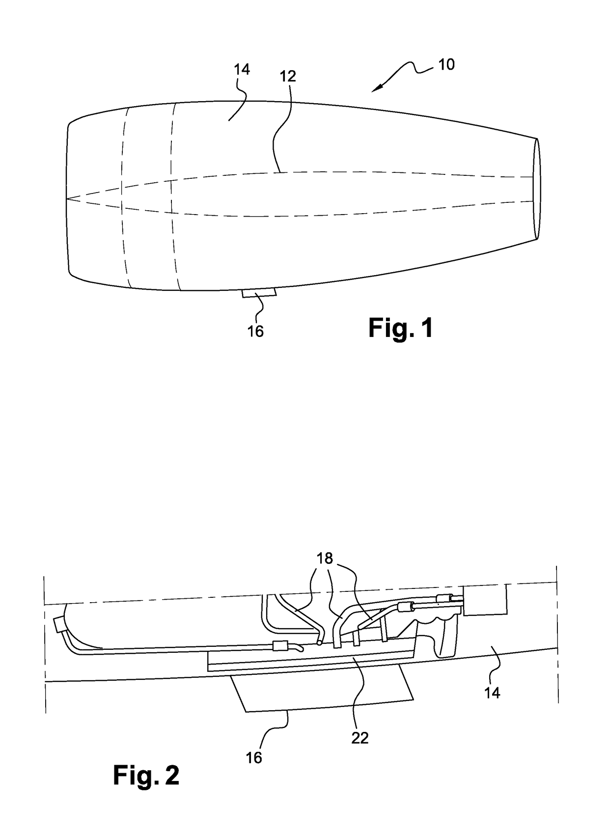
[0033]Reference is made first of all to FIG. 1, which depicts an aircraft propulsion unit 10 comprising an engine 12 (such as a bypass turbojet engine, depicted schematically by broken lines) mounted inside a nacelle 14.

[0034]The engine 12 comprises, from upstream to downstream in the direction of flow of the gases (from left to right in the drawing), an air inlet, a fan, at least one compressor, a combustion chamber, at least one turbine and a duct for ejecting the combustion gases. The nacelle 14 comprises cowls that define the external surface of the propulsion unit.

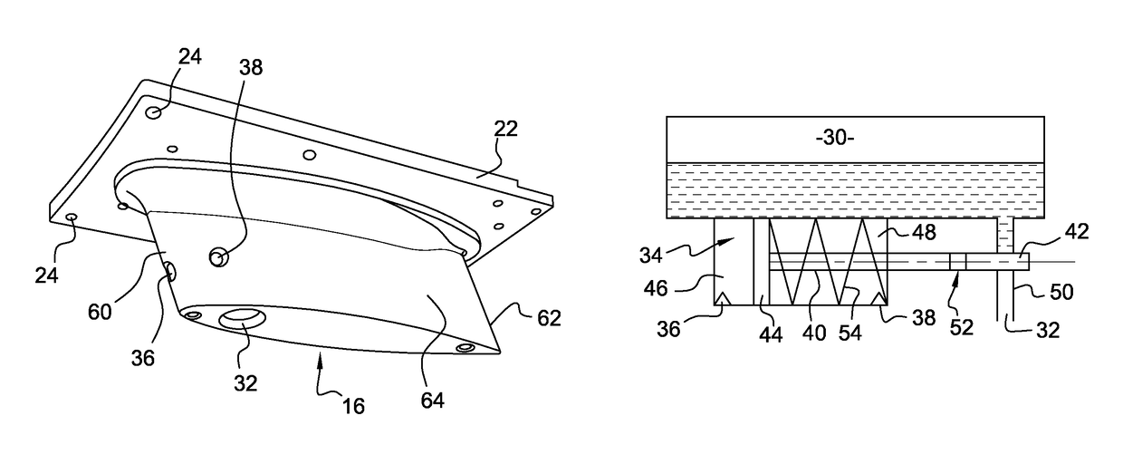
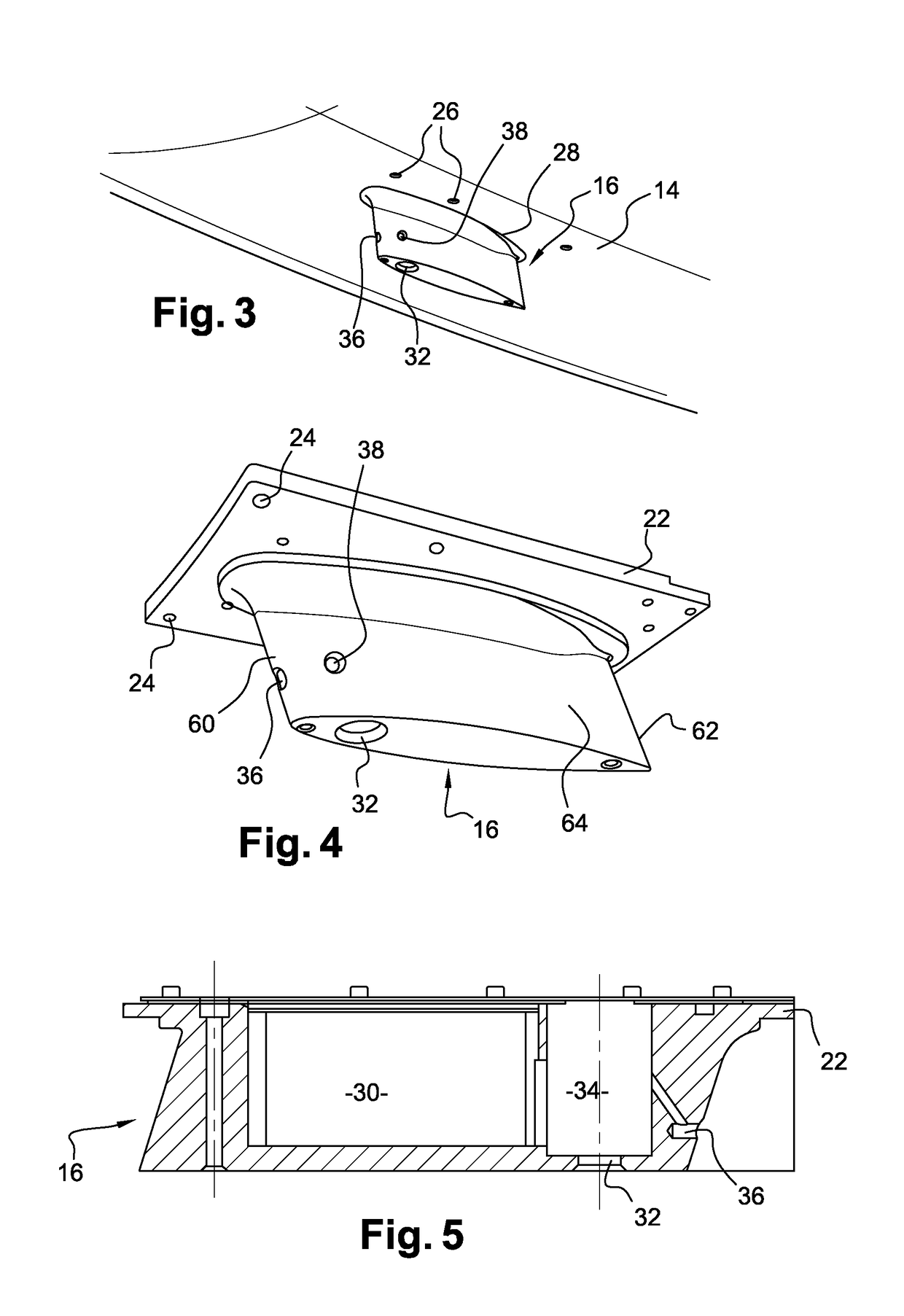
[0035]The turbine engine 10 comprises a stub 16 for discharging drained fluids, this stub has a substantially radial orientation (with respect to the longitudinal axis of the propulsion unit) and projects on the external surface of the nacelle 14. It is situated at the bottom part of the propulsion unit, at 6 o'clock by analogy with the dial of a clock.

[0036]A plurality of types of fluid circulate in the turbine engin...


PUM

PropertyMeasurementUnit
pressureaaaaaaaaaa
pressureaaaaaaaaaa
pressureaaaaaaaaaa

Abstract

Stub for discharging drained fluids for a propulsion unit. The stub includes a cavity for storing the drained fluids and at least one orifice for discharging the fluids contained in the storage cavity, and elements for measuring a difference in pressure outside the stub and a member for draining the storage cavity. The member is able to move between a first position of closing the discharge orifice and a second position of releasing the orifice, and is configured so as to move from the first to the second position when the difference in pressure is greater than, or equal to, a predetermined value.

Description

TECHNICAL FIELD[0001]The present invention relates to a stub for discharging drained fluids for an aircraft propulsion unit comprising in particular an engine (such as a turbojet engine or a turboprop engine) surrounded by a nacelle.PRIOR ART[0002]An aircraft propulsion unit is in general equipped with means for draining fluids (oil, water and / or fuel) from the engine in order to prevent these fluids accumulating and interfering with the functioning of the engine. The oil and fuel are drained by means of dynamic seal technologies (pumps, AGB, metering devices, actuators, etc.) not affording a perfect seal. It is therefore necessary to drain the fluids that pass through the dynamic seals in order to prevent leakages in the engine. The water is drained in order to avoid retention zones, which often cause corrosion.[0003]In the prior art, the drained fluids may be discharged directly outside. The means for draining fluids from the engine may also be connected by conveying means, such a...

Claims


Application Information

Patent Timeline
Patent Type & Authority Patents(United States)
IPC IPC(8): B64C1/14F02C7/30F01D25/32B64D29/00G01L7/00
CPCB64C1/1453B64D29/00F01D25/32G01L7/00F02C7/30Y10T137/2012F05D2220/323
Inventor LEON, ALEXANDREPAVILLET, JULIENSAYN-URPAR, JULIEN
Owner SN DETUDE & DE CONSTR DE MOTEURS DAVIATION S N E C M A
Why Eureka
Try Eureka