Supercharge Your Innovation With Domain-Expert AI Agents!

Leaf seal reach over spring with retention mechanism

a technology of sealing assembly and seal, which is applied in the direction of machines/engines, efficient propulsion technologies, and stators. it can solve the problems of material fatigue of checkmark springs, less favorable thermal properties of stationary components positioned radially outward from the hot gas path,

Active Publication Date: 2018-07-31
GENERAL ELECTRIC CO
View PDF20 Cites 0 Cited by
  • Summary
  • Abstract
  • Description
  • Claims
  • Application Information

AI Technical Summary

Benefits of technology

The technical effects of this patent text are not specified, but it aims to provide a detailed description of an invention and its advantages. The invention can be seen as a way to address a specific problem or improve a certain process. However, without further information, it is difficult to determine the specific technical effects of the invention.

Problems solved by technology

Nevertheless, the stationary components positioned radially outward from the hot gas path (e.g., casing) may have less favorable thermal properties.
However, checkmark springs may experience material fatigue.

Method used


Image

  • Leaf seal reach over spring with retention mechanism
  • Leaf seal reach over spring with retention mechanism
  • Leaf seal reach over spring with retention mechanism

Examples


Embodiment Construction

[0016]Reference will now be made in detail to present embodiments of the invention, one or more examples of which are illustrated in the accompanying drawings. The detailed description uses numerical and letter designations to refer to features in the drawings. Like or similar designations in the drawings and description have been used to refer to like or similar parts of the invention. As used herein, the terms “first”, “second”, and “third” may be used interchangeably to distinguish one component from another and are not intended to signify location or importance of the individual components. The terms “upstream” and “downstream” refer to the relative flow direction with respect to fluid flow in a fluid pathway. For example, “upstream” refers to the flow direction from which the fluid flows, and “downstream” refers to the flow direction to which the fluid flows.

[0017]Each example is provided by way of explanation of the invention, not limitation of the invention. In fact, it will ...


PUM


Abstract

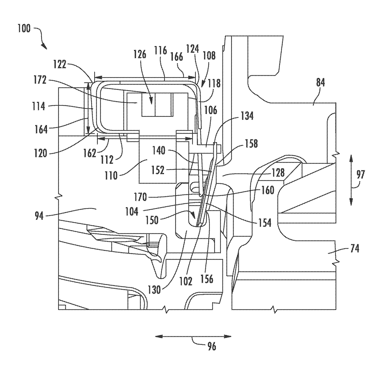
A gas turbine sealing assembly includes a first static gas turbine wall, a second static gas turbine wall, and a leaf seal having a first side and a second side. The first static gas turbine wall contacts the second side at a first position, and the second static gas turbine wall contacts the second side at a second position. A spring exerts force on the first side. The spring includes a first spring wall coupled to the first static gas turbine wall. A second spring wall extends radially outward from the first spring wall. A third spring wall extends axially away from the second spring wall. A fourth spring wall extends radially inward from the third spring wall and includes a radially inner end. The radially inner end of the fourth spring wall contacts the first side of the leaf seal between the first position and the second position.

Description

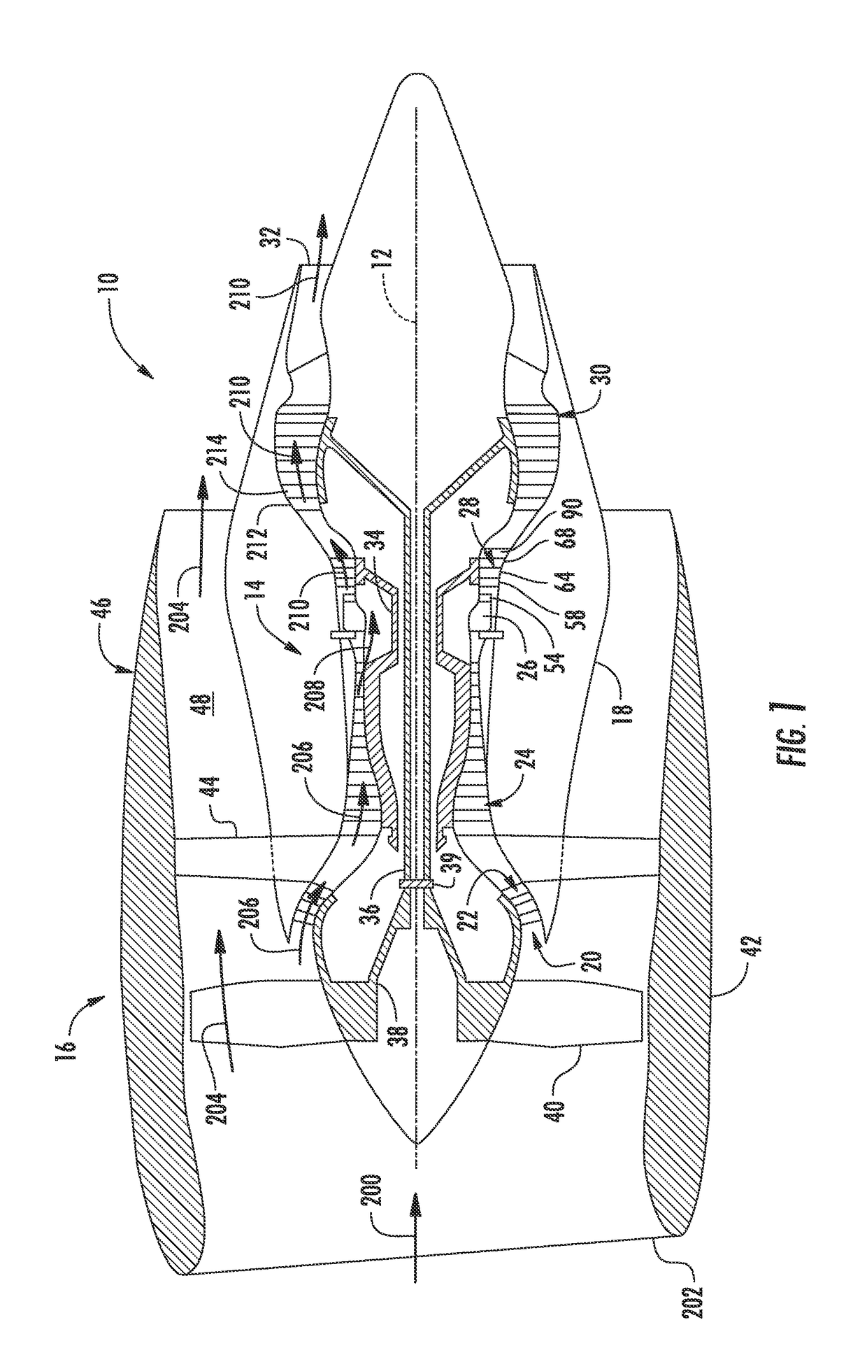
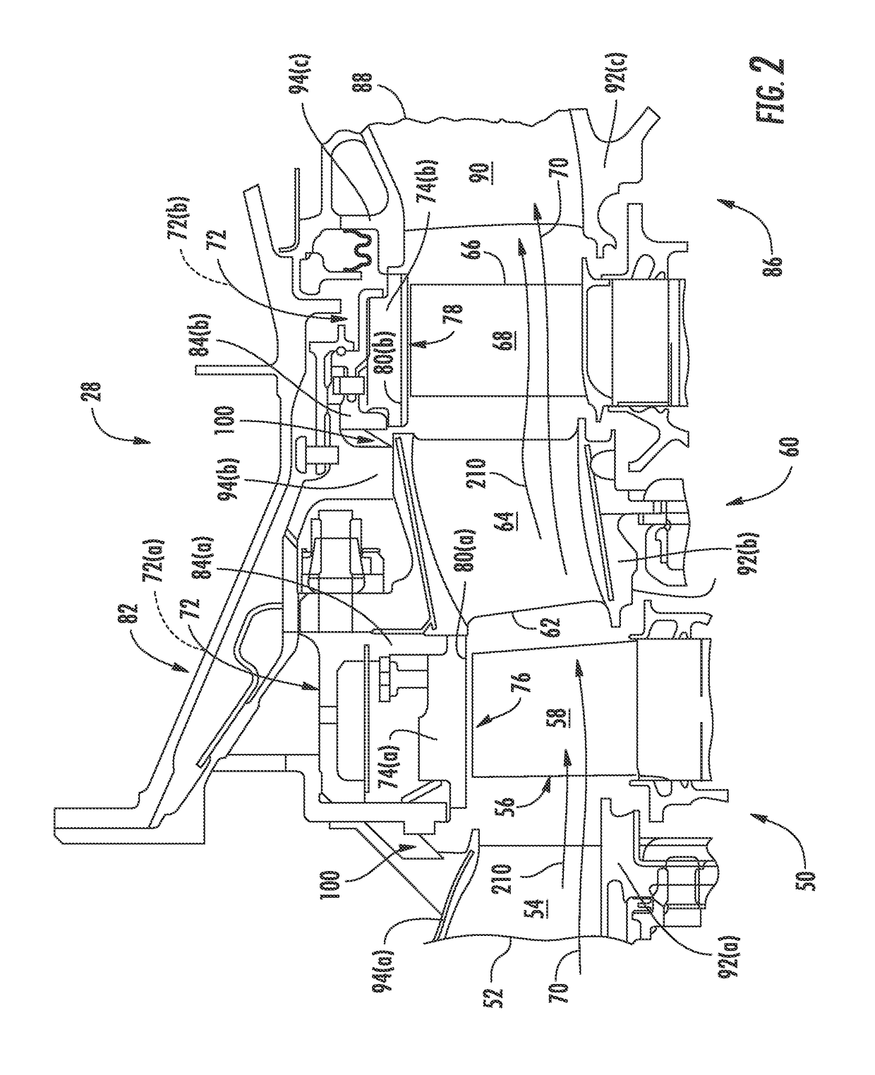
FIELD OF THE INVENTION[0001]The present subject matter relates generally to a sealing assembly for a gas turbine engine. More particularly, the present subject matter relates to a sealing assembly for adjacent stationary components of a gas turbine engine having a spring for securing a leaf seal.BACKGROUND OF THE INVENTION[0002]A gas turbine engine generally includes, in serial flow order, a compressor section, a combustion section, a turbine section, and an exhaust section. In operation, air enters an inlet of the compressor section where one or more axial compressors progressively compress the air until it reaches the combustion section. Fuel mixes with the compressed air and burns within the combustion section, thereby creating combustion gases. The combustion gases flow from the combustion section through a hot gas path defined within the turbine section and then exit the turbine section via the exhaust section.[0003]In particular configurations, the turbine section includes, in...

Claims


Application Information

Patent Timeline
Patent Type & Authority Patents(United States)
IPC IPC(8): F01D11/00F02C7/28F16J15/08F02C3/04F01D9/04F01D25/24F01D15/12
CPCF01D11/005F01D11/00F01D11/003F01D15/12F01D25/246F02C3/04F02C7/28F16J15/0887F01D9/04Y02T50/672F05D2220/32F05D2240/11F05D2240/57F05D2240/80F05D2260/30Y02T50/60
Inventor UGARTE, JOHNNATTAN TENNESSEESENILE, DARRELL GLENNSRINIVAS, MULLAHALLI VENKATARAMANIAHFARMER, JONATHONQUILL, HUGH
Owner GENERAL ELECTRIC CO
Features
  • R&D
  • Intellectual Property
  • Life Sciences
  • Materials
  • Tech Scout
  • Unparalleled Data Quality
  • Higher Quality Content
  • 60% Fewer Hallucinations
Learn More