Non-pneumatic support structure

a support structure and non-pneumatic technology, applied in the direction of spoked wheels, transportation and packaging, with multiple inflatable chambers, etc., can solve the problems of limited performance of pneumatic tires, significant reduction of load carrying capacity of pneumatic tires,

Active Publication Date: 2018-08-07
THE GOODYEAR TIRE & RUBBER CO
View PDF38 Cites 14 Cited by
  • Summary
  • Abstract
  • Description
  • Claims
  • Application Information

AI Technical Summary

Benefits of technology

[0009]According to yet another aspect of the assembly, the assembly further comprises a reinforcing layer interlaced circumferentially and radially about the plurality of cavities and alternating openings for further tuning the flexibility / stiffness of the structure.
[0016]According to yet another aspect of the method, another step interlaces a reinforcing layer circumferentially and radially about the plurality of cavities for further tuning the flexibility / stiffness of the spoke structure.

Problems solved by technology

If air pressure is lost, load carrying capacity of a pneumatic tire decreases significantly.
Preventing the slow or sudden air pressure loss has been a challenge for the tire makers.
Due to the characteristics of the polymeric materials used in the spokes of these tires, performance of these tires are limited.

Method used


Image

  • Non-pneumatic support structure
  • Non-pneumatic support structure
  • Non-pneumatic support structure

Examples


Embodiment Construction

OF THE PRESENT INVENTION

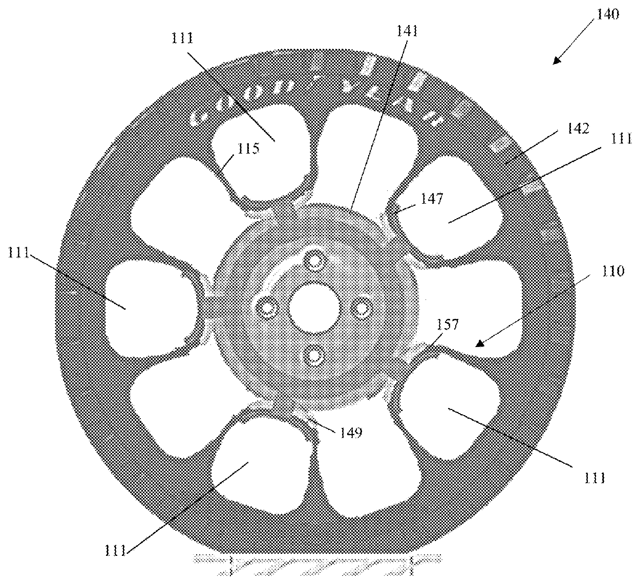
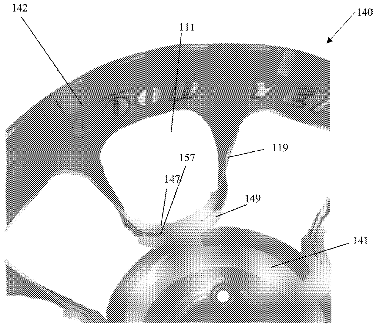
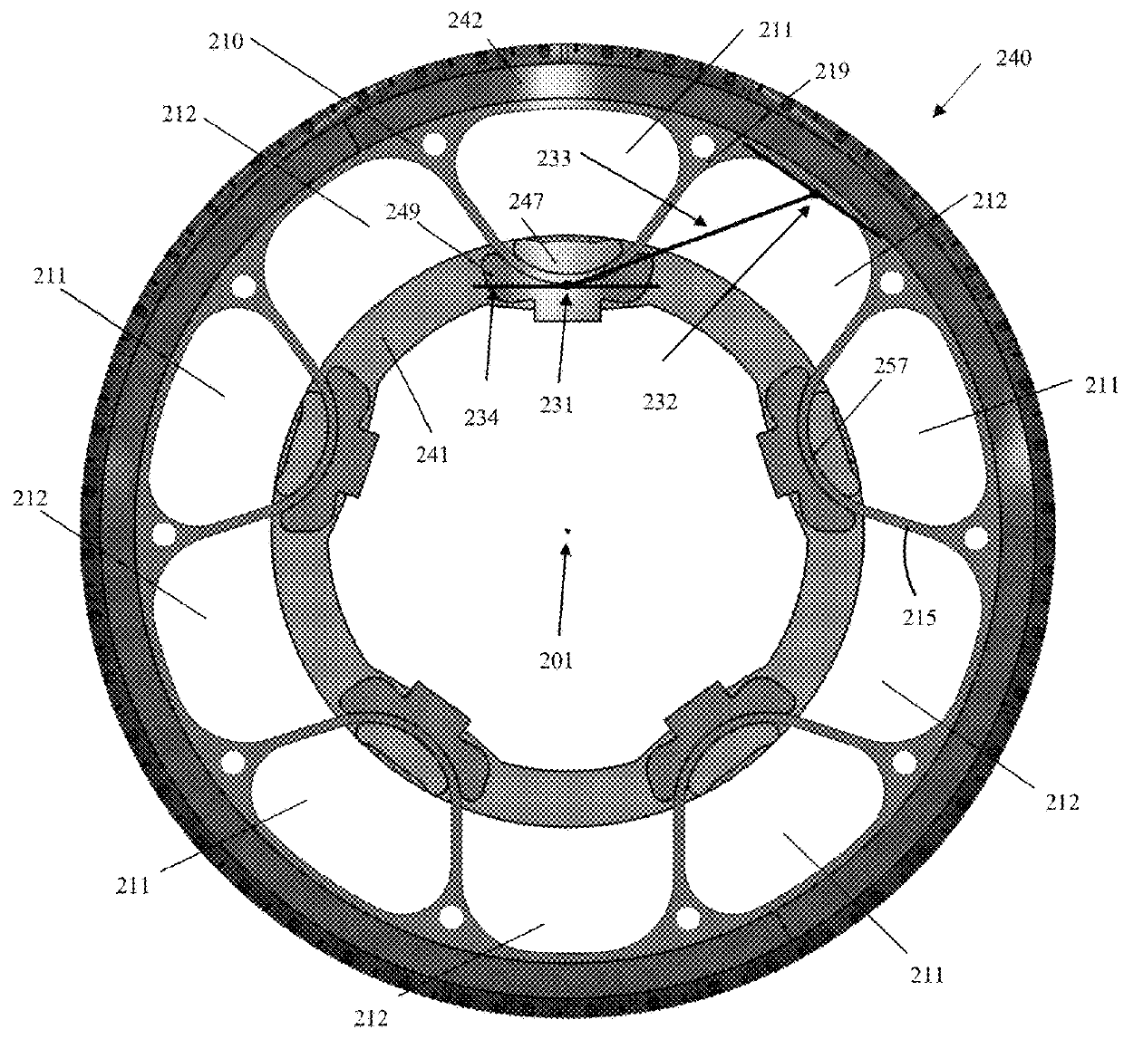
[0025]A conventional wheel / tire assembly, such as that described in US 2004 / 0069385, incorporated herein by reference in its entirety, may have an outer ring, such as a shear band, flexibly connected to a central hub by means of lightweight composite springs. The springs may be plates fixed to the ring and to the hub. The hub may contain a speed reduction gear unit and / or an electric motor and may have a suspension mechanism for connecting a vehicle chassis to each wheel. The ring may be constructed from a flexible composite material, such as carbon fiber reinforced nylon material and have twin rubber tires and a plurality of circumferentially spaced-apart radial cleats which engage the ground and provide improved traction. The hub may also be formed from a carbon fiber reinforced composite material. Another conventional wheel may have a rubber strip with a molded tread bonded to a composite ring for improved grip. Further, the springs interconnecting the rin...


PUM


Abstract

A wheel and tire assembly for a mobile vehicle in accordance with the present invention includes an inner central rim, a flexible ring mounted on the inner central rim, and a spoke structure extending between the inner central rim and the flexible ring. The spoke structure defines a plurality of cavities and alternating radially extending openings disposed concentrically about the inner central rim and allowing the flexible ring to deflect under load.

Description

FIELD OF INVENTION[0001]The present invention relates to wheel / tire assemblies, and more particularly, to non-pneumatic wheel / tire assemblies.BACKGROUND OF THE INVENTION[0002]Radial pneumatic tires rely on the ply reinforcement to carry and transfer the load between the rim and the belt layer. These ply cords need to be tensioned to carry the load. Tensioning of these ply cords is achieved with the pressurized air in the inner chamber of the tire. If air pressure is lost, load carrying capacity of a pneumatic tire decreases significantly. Preventing the slow or sudden air pressure loss has been a challenge for the tire makers. One proposed solution is to use non-pneumatic tires. A top loader non-pneumatic tire can perform similar to a pneumatic tire if its durability, speed rating / limit and load capacity can be increased to the levels of a pneumatic tire.[0003]Many top loader non-pneumatic tires rely on the polymeric spokes to carry the load of the vehicle. Spokes transfer the load ...

Claims


Application Information

Patent Timeline
Patent Type & Authority Patents(United States)
IPC IPC(8): B60C7/14B60C7/18B60C7/12B60B9/26B60B1/02B60C7/10
CPCB60B1/0276B60B9/26B60C7/18B60C7/12B60C7/14B60C2007/146B60C2007/107B60C5/20B60C9/02B60C7/146B60C7/107B60C7/10
Inventor CELIK, CEYHAN
Owner THE GOODYEAR TIRE & RUBBER CO
Why Eureka
Try Eureka