Electric power steering device and electric power steering system

a technology of electric power steering and steering device, which is applied in the direction of power steering, electric steering, vehicle components, etc., can solve the problems of reducing the power supply voltage, unable to perform the current limitation suitable during cranking, and limiting the steering assist, so as to prevent excessive power supply voltage drop and shorten the time period

Active Publication Date: 2018-08-28
TOYOTA JIDOSHA KK
View PDF10 Cites 3 Cited by
  • Summary
  • Abstract
  • Description
  • Claims
  • Application Information

AI Technical Summary

Benefits of technology

[0019]In the cranking upper limit characteristic, the upper limit limitation on the current caused to pass through the motor is relaxed as compared with the non-cranking upper limit characteristic. Consequently, it is possible to prevent excessive current limitation during cranking. As a result, according to the above aspects, it is possible to appropriately perform the current limitation during cranking and the current limitation during non-cranking. With this, it is possible to improve a steering operation feeling while suppressing the decrease of the voltage of the vehicle-mounted power supply. It should be noted that the description “the current upper limit value is set based on the power supply voltage” is not limited to a configuration in which the current upper limit value is set based on the power supply voltage itself (including the history of the power supply voltage), but may include a configuration in which the current upper limit value is set based on, e.g., the power supply voltage and a change rate (a differential value) of the power supply voltage.
[0035]According to the aspects, similarly to the case during non-cranking, it is possible to impose the strict current limitation under a situation where the power supply voltage is decreasing even during cranking. Consequently, it is possible to prevent excessive drop of the power supply voltage. In addition, the current limitation is relaxed as compared with the current limitation during non-cranking after the power supply voltage starts to increase, and hence it is possible to shorten the time period when the steering assist is limited by the current limitation. It should be noted that, with regard to the description “the same current upper limit value is set in each of the cranking upper limit characteristic and the non-cranking upper limit characteristic”, the current upper limit value in the cranking upper limit characteristic may be the same as the current upper limit value in the non-cranking upper limit characteristic, and the matching of the current upper limit values is not limited to perfect matching.

Problems solved by technology

In the case where a control system is configured such that steering assist control is continued even during the stop of the engine, there are cases where the steering assist is limited by the above current limitation resulting from the decrease of the power supply voltage during cranking.
As a result, when the upper limit characteristic that is strictly set as described above is used without any alteration and the current limitation is executed, a time period when the steering assist is limited, i.e., a time period when the operation feeling of the steering wheel is heavy is prolonged unnecessarily so that it becomes impossible to perform the current limitation suitable during cranking.

Method used


Image

  • Electric power steering device and electric power steering system
  • Electric power steering device and electric power steering system
  • Electric power steering device and electric power steering system

Examples


Embodiment Construction

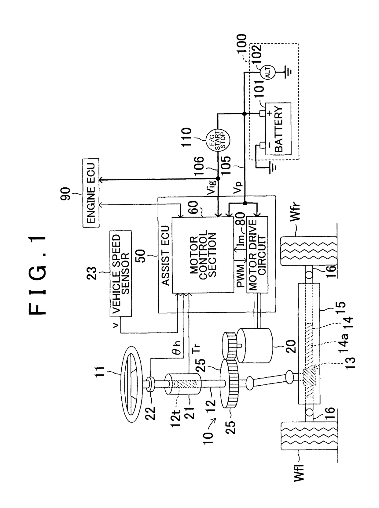
[0045]Hereinbelow, an electric power steering device according to an embodiment of the invention will be described by using the drawings. FIG. 1 shows the schematic configuration of the electric power steering device of a vehicle as the embodiment.

[0046]The electric power steering device includes a steering mechanism 10 that turns a turning wheel by a steering operation of a steering wheel 11, a motor 20 that generates a steering assist torque, and an ECU 50 that controls the operation of the motor 20. Hereinafter, the ECU 50 is referred to as an assist ECU 50.

[0047]The steering mechanism 10 is configured so as to convert rotation of a steering shaft 12 about an axis that is interlocked with the rotation operation of the steering wheel 11 to a stroke motion of a rack bar 14 in a left and right direction using a rack and pinion mechanism 13, and turn a left front wheel Wfl and a right front wheel Wfr with the stroke motion.

[0048]A gear section 14a of the rack bar 14 is accommodated i...


PUM


Abstract

A characteristic selection / current upper limit value calculation section 64 selects a cranking upper limit characteristic map MP2 in the case where a cranking state is detected by a cranking state supposition section 63, and selects a non-cranking upper limit characteristic map MP1 in the case where the cranking state is not detected. Upper limit limitation on a current caused to pass through a motor 20 is relaxed in a cranking upper limit characteristic as compared with a non-cranking upper limit characteristic. Consequently, it is possible to prevent excessive current limitation during cranking.

Description

BACKGROUND OF THE INVENTION[0001]1. Field of the Invention[0002]The invention relates to an electric power steering device an electric power steering system that drive a motor based on a steering operation of a driver to generate a steering assist torque.[0003]2. Description of Related Art[0004]There is an electric power steering device that controls an energization amount of a motor in accordance with a steering torque applied to a steering wheel by a driver to generate a steering assist torque. In such an electric power steering device, in the case where the driver performs a steering operation strongly, a large current flows from a vehicle-mounted power supply to the motor. When the vehicle-mounted power supply is degraded, an output voltage (power supply voltage) of the vehicle-mounted power supply decreases during energization of the motor. As the degree of degradation of the vehicle-mounted power supply is larger, the decrease of the power supply voltage to the current flowing...

Claims


Application Information

Patent Timeline
Patent Type & Authority Patents(United States)
IPC IPC(8): B62D5/04B62D6/10
CPCB62D5/0463B62D6/10B62D5/0412B62D5/0481
Inventor SONE, ATSUSHI
Owner TOYOTA JIDOSHA KK
Why Eureka
Try Eureka