Printing method, printing apparatus, printing system, and storage medium

a printing system and printing method technology, applied in printing, other printing apparatus, etc., can solve problems such as insufficient operation of piezo elements, and achieve the effect of suppressing the drop in voltag

Active Publication Date: 2009-09-08
SEIKO EPSON CORP
View PDF5 Cites 2 Cited by
  • Summary
  • Abstract
  • Description
  • Claims
  • Application Information

AI Technical Summary

Benefits of technology

[0007]The present invention was arrived at in light of the foregoing issues, and it is an object thereof to achieve a printing method that can suppress the drop in voltage caused by discharging of the piezo elements.

Problems solved by technology

However, if there are contiguous pixels where dots are not formed, then no drive signals are applied to the piezo elements during that time, and thus the piezo elements are discharged and their voltage drops.
Such a sharp change in voltage may result in the piezo elements not operating properly.

Method used


Image

  • Printing method, printing apparatus, printing system, and storage medium
  • Printing method, printing apparatus, printing system, and storage medium
  • Printing method, printing apparatus, printing system, and storage medium

Examples


first embodiment

[0113]In the first embodiment, an example is described in which the piezo elements 417 are charged using, for example, an “all-on” signal (forced application signal) which causes the drive signal COM to be applied to the piezo elements 417.

[0114]FIG. 16A is a diagram describing the prevention circuit 90 according to the present embodiment. FIG. 16B is a truth value table for describing functions of the prevention circuit 90.

[0115]When using the two original drive signals COM_A and COM_B, the prevention circuit 90 outputs a switch operation signal SD (a first switch operation signal SD_A and a second switch operation signal SD_B) based on the first selection data which corresponds to the first original drive signal COM_A, the second selection data which corresponds to the second original drive signal COM_B, and the “all-on” signal (forced application signal). Here, the “all-on” signal (forced application signal) is a signal which causes the switch operation signal SD for operating th...

second embodiment

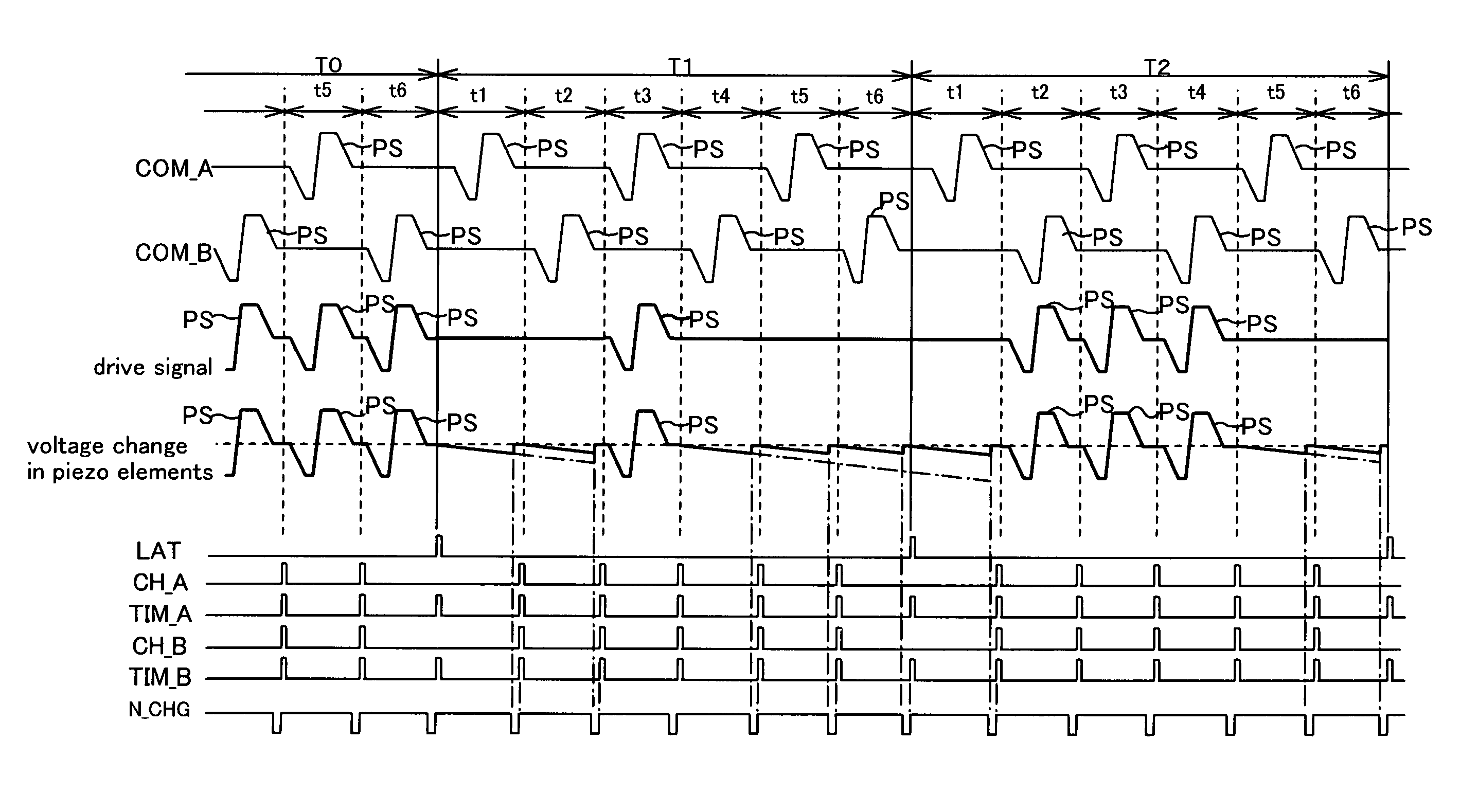
[0141]In the above first embodiment, an example was described in which the “all-on” signal N_CHG is used as a signal for charging the piezo elements, but in the second embodiment, twelve-bit data is adopted as the selection data generated based on the print data. Specifically, the time periods t1 through t6 of the first embodiment are each divided into two time periods by the change signals CH_A and CH_B. Then, as for one of the divided time periods, new change signals CH_Aa and CH_Ba are generated at a timing approximately 2 to 4 μsec immediately before the timing signals TIM_A and TIM_B which act as triggers for the next time period, and new time periods are set therebefore and thereafter. In other words, the time periods t1 through t6 of the first embodiment are each divided into a main time period ta before the new change signals CH_Aa and CH_Ba and a micro time period tb after the new change signals CH_Aa and CH_Ba, and the selection data is set in these. During the micro time ...


PUM


Abstract

A printing method that can suppress drops in voltage due to discharging of piezo elements is achieved. A printing method includes: generating a drive signal for driving a piezo element by selecting, based on print data, either a first original drive signal having a unit signal for defining the start to the end of an operation of causing the piezo element to eject ink by changing a voltage of the piezo element using a first reference voltage as a reference, or a second original drive signal having a unit signal for defining the start to the end of an operation of causing the piezo element to eject ink by changing the voltage of the piezo element using a second reference voltage as a reference; ejecting ink using the piezo element by applying the generated drive signal thereto to charge / discharge the piezo element; and charging the piezo element so that the voltage thereof attains either the first or second reference voltage during a predetermined period during which neither the first nor the second original drive signal is selected.

Description

CROSS-REFERENCE TO RELATED APPLICATIONS[0001]The present application claims priority upon Japanese Patent Application No. 2004-282641 filed on Sep. 28, 2004, which is herein incorporated by reference.BACKGROUND OF THE INVENTION[0002]1. Field of the Invention[0003]The present invention relates to printing methods, printing apparatuses, printing systems, and storage media.[0004]2. Description of the Related Art[0005]Some types of printing apparatuses for printing images on media are provided with piezo elements for ejecting ink by being charged and discharged based on a plurality of drive signals. For example, JP 2000-52570A discloses a printing apparatus in which a plurality of types of drive pulses, each corresponding to a different ejection amount of ink, are divided up and included in two original drive signals, and in which printing is performed based on drive signals generated by selecting, from the two original drive signals, the drive pulses to be applied to the piezo elements...

Claims


Application Information

Patent Timeline
Patent Type & Authority Patents(United States)
IPC IPC(8): B41J29/38
CPCB41J2/0452B41J2/04573B41J2/04595B41J2/04588B41J2/04581
Inventor USUI, TOSHIKI
Owner SEIKO EPSON CORP
Why Eureka
Try Eureka