Power conversion device and power conversion method

a technology of power conversion device and power conversion method, which is applied in the direction of electric variable regulation, process and machine control, instruments, etc., can solve the problem of achieve the effect of suppressing the voltage decrease of each por

Active Publication Date: 2016-09-06
TOYOTA JIDOSHA KK
View PDF21 Cites 2 Cited by
  • Summary
  • Abstract
  • Description
  • Claims
  • Application Information

AI Technical Summary

Benefits of technology

[0007]Therefore, an aspect of the invention provides for suppressing voltage decrease of each port.
[0009]According to the aspect of the invention, it is possible to suppress the voltage decrease of each port.

Problems solved by technology

When the transmission efficiency is degraded, it is difficult to transmit desired power between the primary side conversion circuit and the secondary side conversion circuit, and a voltage of each port may decrease.

Method used


Image

  • Power conversion device and power conversion method
  • Power conversion device and power conversion method
  • Power conversion device and power conversion method

Examples


Embodiment Construction

101>

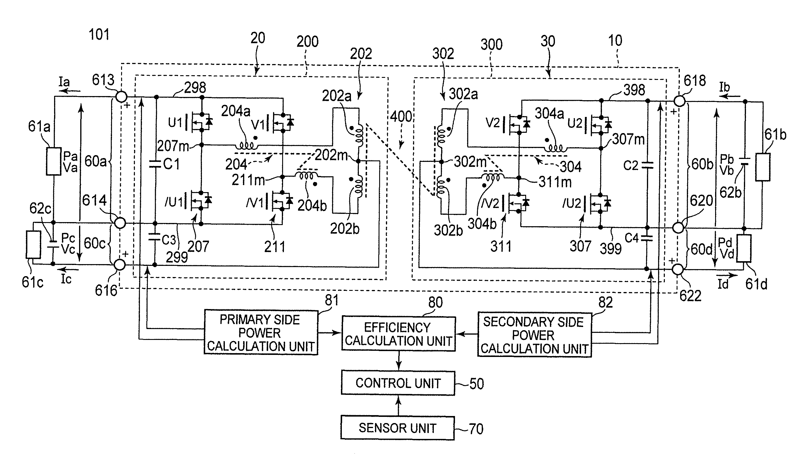
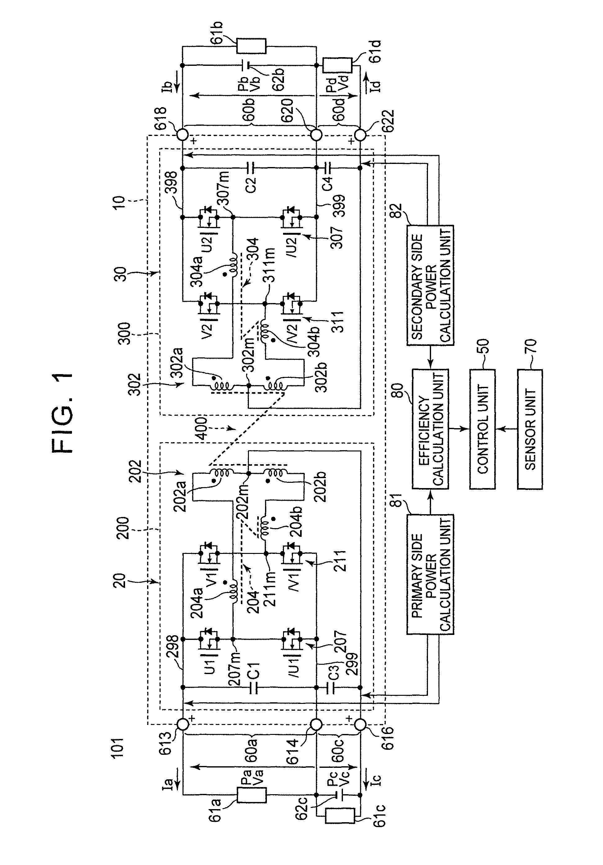
[0016]FIG. 1 is a block diagram illustrating a configuration example of a power supply device 101 as an embodiment of a power conversion device. The power supply device 101 is, for example, a power supply system including a power supply circuit 10, a control unit 50, and a sensor unit 70. The power supply device 101 is a system that is mounted on a vehicle such as an automobile and that distributes power to in-vehicle loads. Specific examples of the vehicle include a hybrid vehicle, a plug-in hybrid vehicle, and an electric automobile.

[0017]For example, the power supply device 101 includes a first input / output port 60a connected to a primary side high voltage system load (for example, an electric power steering device (EPS)) 61a and a second input / output port 60c connected to a primary side low voltage system load (for example, an electronic control unit (ECU) and an electronic control brake system (ECB)) 61c and a primary side low voltage system power supply (for example, an au...


PUM


Abstract

A power conversion method of a power conversion device including a plurality of primary side ports disposed in a primary side circuit and a plurality of secondary side ports disposed in a secondary side circuit magnetically coupled to the primary side circuit with a transformer, the power conversion device adjusting transmission power transmitted between the primary side circuit and the secondary side circuit by changing a phase difference between switching of the primary side circuit and switching of the secondary side circuit, the power conversion method including: calculating a transmission efficiency setting an adjustment value of the phase difference to a value obtained by dividing the transmission efficiency by a specified efficiency; and setting the phase difference to a value obtained by dividing the calculated value by the adjustment value when the adjustment value is less than the specified value.

Description

INCORPORATION BY REFERENCE[0001]The disclosure of Japanese Patent Application No. 2014-080485 filed on Apr. 9, 2014 including the specification, drawings and abstract is incorporated herein by reference in its entirety.BACKGROUND OF THE INVENTION[0002]1. Field of the Invention[0003]The present invention relates to a power conversion device and a power conversion method.[0004]2. Description of Related Art[0005]A power conversion device is known which adjusts transmission power transmitted between a primary side conversion circuit including a plurality of primary side ports and a secondary side conversion circuit including a plurality of secondary side ports and being magnetically coupled to the primary side conversion circuit with a transformer depending on a phase difference φ (for example, see Japanese Patent Application Publication No. 2011-193713 (JP 2011-193713 A)).[0006]However, the transmission power that is adjusted depending on the phase difference φ is also affected by a tr...

Claims


Application Information

Patent Timeline
Patent Type & Authority Patents(United States)
IPC IPC(8): H02M3/335H02M1/00
CPCH02M3/33584H02M3/3353H02M2001/0048H02M2001/0064Y02B70/1491H02M3/33561H02M1/0048H02M1/0064Y02B70/10
Inventor HIRANO, TAKAHIRO
Owner TOYOTA JIDOSHA KK
Why Eureka
Try Eureka